Table of Contents
Advertisement
Instruction Manual AVTMTTR310
Transformer Turn Ratio Test Set
Catalog No. TTR310, TTR310-47, TTR310E
Read the entire manual before operating.
Antes de operar este producto lea este manual enteramente.
for
Three-Phase TTR
High-Voltage Equipment
Aparato de Alto Voltaje
AVTMTTR310
Rev 8
May 2016
M
Valley Forge Corporate Center
2621 Van Buren Avenue
Norristown, PA 19403 U.S.A.
610-676-8500
www.megger.com
Advertisement
Table of Contents

Related Manuals for Megger TTR310


Summary of Contents for Megger TTR310
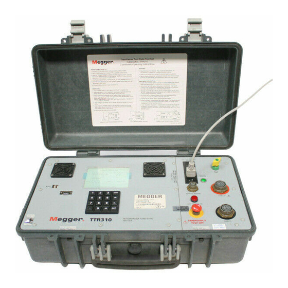
- Page 1 Rev 8 May 2016 Instruction Manual AVTMTTR310 Three-Phase TTR Transformer Turn Ratio Test Set Catalog No. TTR310, TTR310-47, TTR310E High-Voltage Equipment Read the entire manual before operating. Aparato de Alto Voltaje Antes de operar este producto lea este manual enteramente.
- Page 3 Three-Phase TTR 310 Transformer Turn Ratio Test Set Instruction Manual...
- Page 4 Warranty Products supplied by Megger are warranted against defects in material and workmanship for a period of one year following shipment. Our liability is specifically limited to replacing or repairing, at our option, defective equipment. Equipment returned to the factory must be shipped prepaid and insured. This warranty does not include batteries, lamps, or other expendable items, where the original manufacturer's warranty shall apply.
-
Page 5: Table Of Contents
TABLE OF CONTENTS ..............................1 NTRODUCTION ..................................5 AFETY ..............................9 PECIFICATIONS Input Power ..............................9 Pollution Degree ............................9 Protective Devices ............................9 Output Test Voltage and Current ......................9 Test Frequency ............................9 Loading of Test Transformer ......................... 10 Measuring Ranges ............................. - Page 6 7 TTR 300 S DB L ..................91 ERIES OWER ANUAL Operating Instructions for the Multiple Quick Test Form .............. 105 Operating Instructions for the Simple 3PH TTR Form ..............106 Operating Instructions for the 3PH TTR with TAP Changer Form ..........107 ................................
- Page 7 Table of Contents LIST OF ILLUSTRATIONS TTR310 Transformer Turn Ratio test set ......................1 Figure 4-1. Three-Phase TTR310 Test Set Block Diagram ..............16 Figure 4-2. Three-Phase TTR310 Control Panel ..................17 Figure 5-1. Setup for Testing Single-Phase Transformer ................20 Figure 5-2.
- Page 8 LIST OF TABLES Table 5-3. T-type Transformer Winding Phase Relationship ..............31 Table 5-4. ANSI Transformer Winding Phase Relationship ..............37 Table 5-5. CEI/IEC 76-1:1993 Transformer Winding Phase Relationship .......... 49 Table 5-6. Transformer Winding Phase Relationship (Australian Std. 2374, Part 4 - 1982) ....60 Table 7-1.
- Page 9 Make one backup copy of the Software. Copyright – The Software is owned by Megger, and its structure, organization and code are the valuable trade secrets of Megger. The Software is also protected by United States Copyright Law and International Treaty provisions. You must treat the Software just as you would any other copyrighted material, such as a book.
- Page 10 Megger has been advised of the possibility of such damages. In any case, Megger and its suppliers’ entire liability under any provision of this agreement shall be limited to the amount actually paid by you for the SOFTWARE.
- Page 11 2621 Van Buren Avenue Norristown, PA 19403 U.S.A. IMPORTANT! Megger periodically provides updates of software. See our web site www.megger.com to obtain these download updates. SEE ALL OF OUR PRODUCTS, APPLICATION NOTES, FAQ’s BY PRODUCT, AND LOCAL REP INFORMATION ON THE WEB AT: www.megger.com...
- Page 12 MANUAL CONVENTIONS This manual uses the following conventions: Bold indicates emphasis or a heading. Arial Bold denotes the use of a screen button (i.e. click the TTR button). Ctrl+Enter indicates that to perform the function, press both keys simultaneously (i.e. Ctrl+Enter indicates that you hold-down the Control (Ctrl) key while simultaneously striking the Enter key).
-
Page 13: Introduction
Notify Megger of any shortage. Telephone 610-676-8500. Examine the instrument for damage received in transit. If any damage is discovered, file a claim with the carrier at once and notify Megger or its nearest authorized sales representative, giving a detailed description of the damage. - Page 14 C57.12.90 – 2013, IEC 60076-1 and CIGRE TB 445 standards. For three-phase measurements, the test set is connected to all Three-Phases of the transformer to be tested. The TTR310 lead selection circuitry permits automatic measurement of all phases without changing connections. This feature eliminates the need to refer to hook-up charts when testing three-phase transformers.
- Page 15 Three excitation test voltages: 80 V, 40 V, and 8 V. Testing to ANSI, IEC, and Australian standards. Leads marked to ANSI, IEC, and Australian standards. Choice of six languages. Large, easy-to-read LCD shows alphanumeric data Meets the requirements of both the European EMC and Low Voltage Directives.
- Page 16 AVTMTTR310 Rev 8 May 2016...
-
Page 17: Safety
For Cat. No. TTR310/ TTR310E 120 V 10%, single phase, 60 2 Hz For Cat. No. TTR310-47/ TTR310E-47 230 V 10%, single phase, 50 2 Hz The neutral pole must be at ground potential. Before making connection to the power source, determine that the instrument rating matches the voltage of the power source and has a suitable two-pole, three-terminal grounding type connector. - Page 18 Before replacing the fuses, disconnect the power input plug from the live power source. Megger has made formal safety reviews of the initial design and any subsequent changes. This procedure is followed for all new products and covers areas in addition to those included in applicable standards.
- Page 19 Megger considers this an excellent safety practice. Users of equipment should note that high-voltage discharges and other sources of strong electric or magnetic field may interfere with the proper functioning of heart pacemakers.
- Page 20 AVTMTTR310 Rev 8 May 2016...
-
Page 21: Specifications
Cat. No. T TTR310/TTR310E:: Type T, 250 V, 1A (IEC 127 designation) Cat. No. TTR310-47/ TTR310E-47:: Type T, 250 V, 0.5 A (IEC 127 designation) High voltage and low voltage measurement circuit shorting relays Heavy duty varistors and transient voltage suppressors... -
Page 22: Loading Of Test Transformer
Loading of Test Transformer Less than 0.2 VA Measuring Ranges Turn ratio: 80 V ac: 0.8 to 45,000, 5 digit resolution 40 V ac: 0.8 to 25,000, 5 digit resolution 8V ac: 0.8 to 8,000, 5 digit resolution Excitation Current: 0 to 500 mA, 3 digit resolution (±2% of reading +1 digit) Phase Angle ±... -
Page 23: Transformer Winding Phase Relationship
SPECIFICATIONS Transformer Winding Phase Relationship ANSI C57.12.70-2011 CEI/IEC 76-1:2011 AS-2374, Part 4 2003 (Australian Standard) Measuring Time 8 to 20 seconds depending on mode of operation and type of transformer Display 5.7 Inch, color display, text on-screen view, numeric keypad Memory Storage Up to 200 data sets of complete 3 phase results Up to 9 custom transformer settings... - Page 24 Three-Phase TTR 310 Test Set, fully automatic, self- checking, self-calibrating, menu-driven unit 120 V ac ±10%, single phase, 60 ±2 Hz, 100 VA TTR310/TTR310E IEC 1010-1 installation category II 230 V ac ±10%, single phase, 50 ±2 Hz, 100 VA TTR310-47/TTR310E-47...
- Page 25 Cat. No. Ethernet cable for connecting to a PC 36798 (TTR310E only) RS-232C serial cable for connecting to a PC CA-RS232 Hand-held TEST switch assembly for remote 30915-220 (TTR310 only) operation Transformer Vector Voltage Diagrams ANSI Standards 35298 IEC Standards...
- Page 26 Item (Qty) Cat. No. 3-ø Universal 33 ft (10 m), X Extension Lead Set 36486-7 3-ø Universal 33 ft (10 m), H Extension Lead Set 36486-8 3-ø Universal 33 ft (10 m), H and X Extension Lead Set 36486-9 Replacement/spare battery pack for printer 37077 Bushing Clips (each) MC7144...
-
Page 27: Description
A block diagram of the TTR310 test set is shown in Figure 4-1. The excitation voltage transformer converts the main voltage into the test excitation voltage of a transformer. -
Page 28: Figure 4-1. Three-Phase Ttr310 Test Set Block Diagram
The converted output digital signals are applied to the microprocessor. The microprocessor orchestrates all steps of the TTR310 test set operation. It provides proper sequence of operation, gathers and calculates the test results, provides interfacing with the display, RS232/printer port, and the control circuitry. -
Page 29: Figure 4-2. Three-Phase Ttr310 Control Panel
L (lower or left) button, an ENT (enter) button, a decimal point button, and an * (asterisk) button. An audible tone confirms that you have successfully pressed a button. Figure 4-2. Three-Phase TTR310 Control Panel GROUND Wing-nut terminal allows connection of test set to earth ground. - Page 30 CABLE X Plug receptacle for connecting test leads to the low-voltage (X) winding of a transformer. AC POWER On/off power switch and input power receptacle provides 120 V 50/60 Hz power to the test set. 100 VA MAX FUSE IEC 127 T 1 Fuse receptacle and rating.
-
Page 31: Setup And Connections
Setup and Connections General Instructions When testing high-voltage transformers, caution must be used at all times and all safety precautions followed. Read and understand all safety information contained in Section 2, Safety. WARNING Ensure that the transformer to be tested is completely de- energized. -
Page 32: Figure 5-1. Setup For Testing Single-Phase Transformer
4. Connect the heavy-duty clips marked X1 and X2 of the test lead to the corresponding (low-voltage winding) terminals of the transformer under test. Figures 5-1 and 5-2 show test setups for single-phase transformers. Figures 5-3 and 5-4 show test setups for regulators. NOTE: When using a three-phase cable set, connect heavy-duty clips marked H1, H2 and X1, X2 to the corresponding terminals of the transformer under test. -
Page 33: Figure 5-3. Setup For Testing Single-Phase, Type A (Straight Design) Step Voltage Regulator
SETUP AND CONNECTIONS Table 5-1. Test Lead Markings for Single-Phase Transformers Test Lead Marking Transformer Heavy-Duty Test Lead Clip ANSI CEI/IEC Australian Terminal Boot Color Color Voltage Band High High Yellow Black Black Yellow Figure 5-3. Setup for Testing Single-Phase, Type A (Straight Design) Step Voltage Regulator AVTMTTR310 Rev 8 May 2016... -
Page 34: Figure 5-4. Setup For Testing Single-Phase, Type B (Inverted Design) Step Voltage Regulator
Figure 5-4. Setup for Testing Single-Phase, Type B (Inverted Design) Step Voltage Regulator Three-Phase, Two-Winding Transformers Perform the following setup procedure for three-phase, two-winding transformers: 1. Connect the wing-nut ground terminal of the test set to a low-impedance earth ground using the 15 ft (4.6 m) ground lead supplied. 2. - Page 35 SETUP AND CONNECTIONS The unused H0 and X0 terminals should be kept clear of ground and personnel because they could become energized during the test. Refer to Table 5-2 for test lead markings. With delta connected windings, H0 or X0 is not used. With wye connected windings, a neutral connection is normally available.
- Page 36 Three-Phase, Three-Winding Transformers This type of transformers has primary, secondary and tertiary windings. Primary and secondary windings are tested as a regular three-phase, two-winding transformer. To test tertiary winding, perform the following setup procedure: 1. Connect the wing-nut ground terminal of the test set to a low-impedance earth ground using the 15 ft (4.6 m) ground lead supplied.
-
Page 37: Current Transformers (Cts)
1. Connect the wing-nut ground terminal of the test set to a low-impedance earth ground using the 15-ft (4.6 m) ground cable supplied. 2. Use the TTR310 H and X test leads and connect as follows and as shown in Figure 5-5. -
Page 38: Figure 5-5. Setup For Testing Unmounted Current Transformer
Figure 5-5. Setup for Testing Unmounted Current Transformer Figure 5-6 shows the setup for testing the taps on a multiple-tap CT. Figure 5-6. Setup for Testing Taps on Multiple Tap CT AVTMTTR310 Rev 8 May 2016... -
Page 39: Bushing Current Transformer (Bct) Mounted On Single-Phase, Two-Winding Transformer
1. Connect the wing-nut ground terminal of the test set to a low-impedance earth ground using the 15-ft (4.6 m) ground cable supplied. 2. Use the TTR310 two or four conductor H and X test leads. 3. Short-circuit the winding on the opposite voltage side of the power transformer core, using jumper leads. -
Page 40: Bcts Mounted On Three-Phase Transformers
BCTs Mounted on Three-Phase Transformers A turn-ratio test can be performed on all three BCTs using a single setup. Figure 5-8 shows how to make the proper connections when the BCTs are mounted on a typical delta winding and Figure 5-9 when mounted on a typical wye winding. 1. -
Page 41: Figure 5-8. Setup For Testing Bct Mounted On Delta Winding On A Three-Phase Power
SETUP AND CONNECTIONS Figure 5-8. Setup for Testing BCT Mounted on Delta Winding on a Three-Phase Power Transformer AVTMTTR310 Rev 8 May 2016... -
Page 42: Figure 5-9. Setup For Testing Bct Mounted On Wye Winding Of A Three-Phase Transformer
Figure 5-9. Setup for Testing BCT Mounted on Wye Winding of a Three-Phase Transformer AVTMTTR310 Rev 8 May 2016... -
Page 43: T-Type Transformers
In this case, the jumpers indicated in Table 5-3 should be applied to the appropriate terminals of the T- type transformers. The TTR310 measured turn ratio should be compared to the calculated turn ratio indicated in Table 5-3. -
Page 44: Connections And Vector Voltage Diagrams
The TTR310 is also capable of measuring the turn ratio on three-phase transformers with an inaccessible neutral point. In this case, the TTR310 automatically shorts an appropriate transformer winding, listed in the winding shorted column of the table. - Page 45 The low-voltage winding lag may be from 0 to 330 in steps of 30 . The TTR310 test set is capable of measuring the turn ratio of three-phase transformers where the windings are rotated or are connected in various phase displacements from standard.
-
Page 46: Figure 5-10. Winding Connections And Phase Relationship
IEC VECTOR GROUP CODING Dyn1 PHASE DISPLACEMENT 30 LAG IEC VECTOR GROUP CODING Dyn5 PHASE DISPLACEMENT 150 LAG IEC VECTOR GROUP CODING Dyn1 PHASE DISPLACEMENT 30 LAG IEC VECTOR GROUP CODING YNd7 PHASE DISPLACEMENT 210 LAG Figure 5-10. Winding Connections and Phase Relationship AVTMTTR310 Rev 8 May 2016... -
Page 47: Notes To Table 5-4
SETUP AND CONNECTIONS Notes to Table 5-4 Transformer terminal markings for distribution and power transformers marked in accordance with requirements of American National Standard Institute, Inc (ANSI) standard C57.12.70 – 2011. Definition of Symbol Designations External terminals on HV transformer winding. External terminals on LV transformer winding. - Page 48 Additional Transformer Winding Identification External terminal markings for three-phase power transformers with more than two windings are as follows: Third winding (if any). Fourth winding (if any). If unable to find a corresponding diagram for a transformer with, for example, accessible neutral winding but can find the corresponding diagram for the same transformer with no neutral accessible winding, follow the test procedure for the transformer with no neutral accessible winding.
-
Page 49: Ansi Transformer Winding Phase Relationship
SETUP AND CONNECTIONS Table 5-4. ANSI Transformer Winding Phase Relationship Copyright 2009 Megger Winding Connection Winding Tested Winding High- Low- Diag Vector High-Voltage Low-Voltage Phase Shorted Voltage Voltage Measured Group Winding (H) Winding (X) Tested By TTR Winding Winding Turn Ratio... - Page 50 Table 5-4. ANSI Transformer Winding Phase Relationship Copyright 2009 Megger Winding Connection Winding Tested Winding High- Low- Measured Diag Vector High-Voltage Low-Voltage Phase Shorted Voltage Voltage Tested By TTR Winding Winding Turn Ratio Remarks Group Winding (H) Winding (X) Neutral...
- Page 51 SETUP AND CONNECTIONS Table 5-4. ANSI Transformer Winding Phase Relationship Copyright 2009 Megger Winding Connection Winding Tested Winding High- Low- Diag Vector High-Voltage Low-Voltage Phase Shorted Voltage Voltage Measured Group Winding (H) Winding (X) Tested By TTR Winding Winding Turn Ratio...
- Page 52 Table 5-4. ANSI Transformer Winding Phase Relationship Copyright 2009 Megger Winding Connection Winding Tested Winding High- Low- Measured Diag Vector High-Voltage Low-Voltage Phase Shorted Voltage Voltage Tested By TTR Winding Winding Turn Ratio Remarks Group Winding (H) Winding (X) accessible...
- Page 53 SETUP AND CONNECTIONS Table 5-4. ANSI Transformer Winding Phase Relationship Copyright 2009 Megger Winding Connection Winding Tested Winding High- Low- Diag Vector High-Voltage Low-Voltage Phase Shorted Voltage Voltage Measured Group Winding (H) Winding (X) Tested By TTR Winding Winding Turn Ratio...
- Page 54 Table 5-4. ANSI Transformer Winding Phase Relationship Copyright 2009 Megger Winding Connection Winding Tested Winding High- Low- Measured Diag Vector High-Voltage Low-Voltage Phase Shorted Voltage Voltage Tested By TTR Winding Winding Turn Ratio Remarks Group Winding (H) Winding (X) Yz11...
- Page 55 SETUP AND CONNECTIONS Table 5-4. ANSI Transformer Winding Phase Relationship Copyright 2009 Megger Winding Connection Winding Tested Winding High- Low- Diag Vector High-Voltage Low-Voltage Phase Shorted Voltage Voltage Measured Group Winding (H) Winding (X) Tested By TTR Winding Winding Turn Ratio...
- Page 56 Table 5-4. ANSI Transformer Winding Phase Relationship Copyright 2009 Megger Winding Connection Winding Tested Winding High- Low- Measured Diag Vector High-Voltage Low-Voltage Phase Shorted Voltage Voltage Tested By TTR Winding Winding Turn Ratio Remarks Group Winding (H) Winding (X) VREG...
- Page 57 SETUP AND CONNECTIONS Table 5-4. ANSI Transformer Winding Phase Relationship Copyright 2009 Megger Winding Connection Winding Tested Winding High- Low- Diag Vector High-Voltage Low-Voltage Phase Shorted Voltage Voltage Measured Group Winding (H) Winding (X) Tested By TTR Winding Winding Turn Ratio...
- Page 58 Table 5-4. ANSI Transformer Winding Phase Relationship Copyright 2009 Megger Winding Connection Winding Tested Winding High- Low- Measured Diag Vector High-Voltage Low-Voltage Phase Shorted Voltage Voltage Tested By TTR Winding Winding Turn Ratio Remarks Group Winding (H) Winding (X) YNyn8...
-
Page 59: Notes To Table 5-5
SETUP AND CONNECTIONS Notes to Table 5-5 Transformer terminal markings for power transformers marked in accordance with requirements of International Standard CEI/IEC 76-1:2011. Definition of Symbol Designations 1U, 1V, 1W External terminals on HV transformer winding (alternate notation U, V, W). 2U, 2V, 2W External terminals on LV transformer winding (alternate notation u, v, w). - Page 60 Additional Transformer Winding Identification External terminal markings for three-phase power transformers with more than two windings are as follows: 3U, 3V, 3W Third winding (if any). 4U, 4V, 4W Fourth winding (if any). If unable to find a corresponding diagram for a transformer with, for example, accessible neutral winding but can find the corresponding diagram for the same transformer with no neutral accessible winding, follow the test procedure for the transformer with no neutral accessible winding.
-
Page 61: Table 5-5. Cei/Iec 76-1:1993 Transformer Winding Phase Relationship
SETUP AND CONNECTIONS Table 5-5. CEI/IEC 76-1:2011 Transformer Winding Phase Relationship Copyright 2009 Megger Winding Connection Winding Tested Winding High- Low- Diag Vector High-Voltage Low-Voltage Phase Shorted Voltage Voltage Measured Group Winding (U1) Winding (U2) Tested By TTR Winding Winding... - Page 62 Table 5-5. CEI/IEC 76-1:2011 Transformer Winding Phase Relationship Copyright 2009 Megger Winding Connection Winding Tested Winding High- Low- Measured Diag Vector High-Voltage Low-Voltage Phase Shorted Voltage Voltage Tested By TTR Winding Winding Turn Ratio Remarks Group Winding (U1) Winding (U2)
- Page 63 SETUP AND CONNECTIONS Table 5-5. CEI/IEC 76-1:2011 Transformer Winding Phase Relationship Copyright 2009 Megger Winding Connection Winding Tested Winding High- Low- Diag Vector High-Voltage Low-Voltage Phase Shorted Voltage Voltage Measured Group Winding (U1) Winding (U2) Tested By TTR Winding Winding...
- Page 64 Table 5-5. CEI/IEC 76-1:2011 Transformer Winding Phase Relationship Copyright 2009 Megger Winding Connection Winding Tested Winding High- Low- Measured Diag Vector High-Voltage Low-Voltage Phase Shorted Voltage Voltage Tested By TTR Winding Winding Turn Ratio Remarks Group Winding (U1) Winding (U2)
- Page 65 SETUP AND CONNECTIONS Table 5-5. CEI/IEC 76-1:2011 Transformer Winding Phase Relationship Copyright 2009 Megger Winding Connection Winding Tested Winding High- Low- Diag Vector High-Voltage Low-Voltage Phase Shorted Voltage Voltage Measured Group Winding (U1) Winding (U2) Tested By TTR Winding Winding...
- Page 66 Table 5-5. CEI/IEC 76-1:2011 Transformer Winding Phase Relationship Copyright 2009 Megger Winding Connection Winding Tested Winding High- Low- Measured Diag Vector High-Voltage Low-Voltage Phase Shorted Voltage Voltage Tested By TTR Winding Winding Turn Ratio Remarks Group Winding (U1) Winding (U2)
- Page 67 SETUP AND CONNECTIONS Table 5-5. CEI/IEC 76-1:2011 Transformer Winding Phase Relationship Copyright 2009 Megger Winding Connection Winding Tested Winding High- Low- Diag Vector High-Voltage Low-Voltage Phase Shorted Voltage Voltage Measured Group Winding (U1) Winding (U2) Tested By TTR Winding Winding...
- Page 68 Table 5-5. CEI/IEC 76-1:2011 Transformer Winding Phase Relationship Copyright 2009 Megger Winding Connection Winding Tested Winding High- Low- Measured Diag Vector High-Voltage Low-Voltage Phase Shorted Voltage Voltage Tested By TTR Winding Winding Turn Ratio Remarks Group Winding (U1) Winding (U2)
- Page 69 SETUP AND CONNECTIONS Table 5-5. CEI/IEC 76-1:2011 Transformer Winding Phase Relationship Copyright 2009 Megger Winding Connection Winding Tested Winding High- Low- Diag Vector High-Voltage Low-Voltage Phase Shorted Voltage Voltage Measured Group Winding (U1) Winding (U2) Tested By TTR Winding Winding...
-
Page 70: Notes To Table 5-6
Notes to Table 5-6 Transformer terminal markings for power transformers marked in accordance with requirements of Australian Standard 2374, Part 4-2003. Definition of Symbol Designations External terminals on HV transformer winding (A External terminals on LV transformer winding (a External neutral terminal on HV transformer winding. External neutral terminal on LV transformer winding. - Page 71 SETUP AND CONNECTIONS Additional Transformer Winding Identification External terminal markings for three-phase power transformers with more than two windings are as follows: 3A, 3B, 3C Third winding (if any). 4A, 4B, 4C Fourth winding (if any). If unable to find a corresponding diagram for a transformer with, for example, accessible neutral winding but can find the corresponding diagram for the same transformer with no neutral accessible winding, follow the test procedure for the transformer with no neutral accessible winding.
-
Page 72: Transformer
Table 5-6. Transformer Winding Phase Relationship (Australian Std. 2374, Part 4 - 2003) Copyright 2009 Megger Winding Connection Winding Tested Winding High- Low- Diag Vector High-Voltage Low-Voltage Phase Shorted Voltage Voltage Measured Group Winding (HV) Winding (LV) Tested By TTR... - Page 73 SETUP AND CONNECTIONS Table 5-6. Transformer Winding Phase Relationship (Australian Std. 2374, Part 4 - 2003) Copyright 2009 Megger Winding Connection Winding Tested Winding High- Low- Diag Vector High-Voltage Low-Voltage Phase Shorted Voltage Voltage Measured Group Winding (HV) Winding (LV)
- Page 74 Table 5-6. Transformer Winding Phase Relationship (Australian Std. 2374, Part 4 - 2003) Copyright 2009 Megger Winding Connection Winding Tested Winding High- Low- Diag Vector High-Voltage Low-Voltage Phase Shorted Voltage Voltage Measured Group Winding (HV) Winding (LV) Tested By TTR...
- Page 75 SETUP AND CONNECTIONS Table 5-6. Transformer Winding Phase Relationship (Australian Std. 2374, Part 4 - 2003) Copyright 2009 Megger Winding Connection Winding Tested Winding High- Low- Diag Vector High-Voltage Low-Voltage Phase Shorted Voltage Voltage Measured Group Winding (HV) Winding (LV)
- Page 76 Table 5-6. Transformer Winding Phase Relationship (Australian Std. 2374, Part 4 - 2003) Copyright 2009 Megger Winding Connection Winding Tested Winding High- Low- Diag Vector High-Voltage Low-Voltage Phase Shorted Voltage Voltage Measured Group Winding (HV) Winding (LV) Tested By TTR...
- Page 77 SETUP AND CONNECTIONS Table 5-6. Transformer Winding Phase Relationship (Australian Std. 2374, Part 4 - 2003) Copyright 2009 Megger Winding Connection Winding Tested Winding High- Low- Diag Vector High-Voltage Low-Voltage Phase Shorted Voltage Voltage Measured Group Winding (HV) Winding (LV)
- Page 78 AVTMTTR310 Rev 8 May 2016...
-
Page 79: Operation
Data shown on the menus and test screens in Figures 6-1 through 6-16 are for illustrative purposes only. The TTR310 test set menus and test screens are operated by using the keypad on the front panel. On power up, a beep sounds, the test set performs a self-test check, and all hardware and software variables are initialized. -
Page 80: Main Menu Screen (Figure 6-1)
MAIN MENU Screen (Figure 6-1) After a successful self-test check, the main menu screen (Figure 6-1) appears. MAIN MENU DATE (M/D/Y) : 06/15/1998 14:15 1 QUICK TEST SETUP TEST WINDING: 2 FULL TEST SETUP 3 RECALL CUSTOM SETTINGS 7 H-X 4 SYSTEM SETUP MENU 8 H-Y 5 SAVED DATA MENU... - Page 81 5 SAVED DATA MENU: The TTR310 saves up to 200 test results. This menu allows these readings to be recalled for viewing and uploading to a PC. 6 PRINT HEADER: This option will print out a test report header to the printer, if connected.
-
Page 82: Quick Test Setup Screen (Figure 6-2)
QUICK TEST SETUP Screen (Figure 6-2) If 1 (QUICK TEST SETUP) is selected on the main menu, the QUICK TEST SETUP screen (Figure 6-2) appears. QUICK TEST SETUP 1 TRANSFORMER ID: nnnnnnnnnnnn 2 TRANSFORMER TYPE: DIAG 01 1ph0 3 START TEST 4 MAIN MENU ENTER SELECTION FROM KEYPAD Figure 6-2. -
Page 83: Quick Test Result Screens (Figure 6-3 And Figure 6-4)
TO STOP TEST Figure 6-3. Initial Quick Test Result Screen The TEST IN PROGRESS message indicates that the TTR310 test set is performing a test. The test may be interrupted by pressing the EMERGENCY TEST OFF button, located on the front panel. When pressed, the EMERGENCY TEST OFF switch is locked in the off position. -
Page 84: Figure 6-4. Final Quick Test Result Screen
THREE PHASE TRANSFORMER TEST TEST: nnn ID:A13579CV0246 DIAG nn Ddnnn TEST VOLTAGE: 80V RATIO 12.379 12.354 12.287 PHASE (min) Iexc (mA) SELECT: 1-PRINT 2-STORE 3-NEXT TEST 4-REPEAT TEST 5-MAIN MENU Figure 6-4. Final Quick Test Result Screen 1 PRINT: This selection allows the test result to be printed out (on an optional printer or uploaded to PC. -
Page 85: Full Test Setup 1 Screen (Figure 6-5)
Diagram numbers for the most common types of transformers are included on the instruction cards in the lid of the TTR310 test set. When selected, the screen appears the same as Figure 6-5, except for the message at bottom of screen: ENTER TRANSFORMER DIAGRAM NUMBER, REFER TO TABLE ON INSTRUCTION CARD. - Page 86 4 H NAMEPLATE This selection is used to enter the nameplate high voltage VOLTAGE (L-L): (H) rating of the transformer to be tested (L-L stands for line to line). The transformer under test nameplate high voltage is used to calculate the transformer turn ratio when test winding 7 (H-X) or 8 (H-Y) is selected on the Main Menu screen (see Figure 6-1).
-
Page 87: Full Test Setup 2 Screen (Figure 6-6)
OPERATION FULL TEST SETUP 2 Screen (Figure 6-6) If 1 is selected on the FULL TEST SETUP 1 screen, the FULL TEST SETUP 2 screen (Figure 6-6) appears. FULL TEST SETUP 2 CONTINUE X NAMEPLATE VOLTAGE (L-L): 5000 NO. OF H TAPS: 33 NOMINAL VOLTAGE X TAP NO: 17 HIGH VOLTAGE X TAP NO: 33 OR 16R... - Page 88 For this selection, there are two choices NO or YES. PHASES: If NO is chosen, the TTR310 will test all three windings and display the test results as shown in Figure 6-8 (THREE PHASE TRANSFORMER TEST result screen). If YES is chosen, the TTR310 will test the first phase of a transformer and display the test results as shown in Figure 6-9 (Phase A Test Result Screen).
-
Page 89: Full Test Setup 3 Screen (Figure 6-7)
OPERATION FULL TEST SETUP 3 Screen (Figure 6-7) If 1 is selected on the FULL TEST SETUP 2 screen, the FULL TEST SETUP 3 screen appears (Figure 6-7). FULL TEST SETUP 3 TEST: nnn ID:A13579CV0246 DIAG nn Ddnnn 1 H TAP TO BE TESTED: 2 X TAP TO BE TESTED: 3 START TEST 4 PREVIOUS MENU... - Page 90 4 PREVIOUS MENU: This selection will return you to the FULL TEST SETUP 2 screen (Figure 6-6). 5 MAIN MENU: This selection returns you to the MAIN MENU screen (Figure 6-1). AVTMTTR310 Rev 8 May 2016...
-
Page 91: Transformer Test Result Screens (Figure 6-8 And Figure 6-9)
OPERATION Transformer Test Result Screens (Figure 6-8 and Figure 6-9) When test is completed with NO pauses between phases chosen (selection 7, Figure 6-6) the test results are displayed as in Figure 6-8 (Three-Phase Transformer Test Results Screen). THREE PHASE TRANSFORMER TEST TEST: nnn ID:A13579CV0246 DIAG nn Ddnnn TAPS TESTED:... -
Page 92: Figure 6-9. Phase A Test Result Screen
“Select 1 – REPEAT TEST 2 – CONTINUE 3 – ABORT TEST” If REPEAT TEST is selected, the test set will re-test phase B or C. If CONTINUE is selected, the test set will start testing of phase C (if an error message appeared during phase B testing). - Page 93 OPERATION 1 allows repeating of the phase C testing. Selection 2 will bring up the five selections shown in Figure 6-8. If abnormal operating conditions occur during testing a transformer, an error message will appear on the screen. Refer to Error Messages section. If one of these messages appears, verify the abnormal condition by taking a repeat measurement before attempting to take any corrective action.
-
Page 94: Main Menu Screen When A Custom Transformer Setting Recalled (Figure 6-10)
Main Menu Screen When a Custom Transformer Setting Recalled (Figure 6-10) After selection of a custom transformer setting, the MAIN MENU will appear as shown in Figure 6-10. It will display the main parameters of the saved custom settings, including the H and X nameplate voltages, the diagram number and the test set voltage. -
Page 95: System Setup Menu (Figure 6-11)
This selection is for entering the desired test voltage. There are four selections available: AUTO the TTR310 will automatically test at the highest allowable excitation voltage (80 V, 40 V, or 8 V), depending on the transformer excitation current measured. -
Page 96: Language Screen (Figure 6-12)
5 PHASE DISPLAY: This selection allows a choice of the phase display units: DEGREES, CENTIRADS or NONE. If DEGREES is selected, any phase test results below 1 degree will be displayed in minutes. If CENTIRADS is selected, the phase test results will be displayed in centiradians (1 centiradian = 0.573 degrees). -
Page 97: Saved Data Screen (Figure 6-13)
OPERATION SAVED DATA Screen (Figure 6-13) When 5 (SAVED DATA MENU) is selected on the MAIN MENU screen (Figure 6-1), the SAVED DATA screen appears as shown in Figure 6-13. SAVED DATA 1 VIEW READINGS 2 DELETE LAST READING 3 DELETE ALL READINGS 4 TRANSFER READINGS TO PC 5 MAIN MENU ENTER SELECTION FROM KEYPAD... -
Page 98: Recall (Or Save) Custom Transformer Settings (Figure 6-14)
Recall (or Save) Custom Transformer Settings (Figure 6-14) If 3 (RECALL CUSTOM SETTINGS) is selected on the MAIN MENU screen (Figure 6-1), the RECALL CUSTOM SETTINGS screen appears as shown in Figure 6-14. If 8 (SAVE CUSTOM SETTINGS) is selected on the FULL TEST SETUP 2 menu (Figure 6-6), the screen appears the same as in Figure 6-14 except that the headline will be changed to SAVE CUSTOM SETTINGS. -
Page 99: Error Messages
TURNS RATIO TOO LOW, <0.8 This message shows that a transformer under test turn ratio is less than 0.8. The TTR310 is not designed to test a transformer turn ratio under 0.8. PHASE A (or B, or C) TURNS RATIO TOO HIGH This message shows that a transformer under test turn ratio is higher than 10,000 (if 80 V or 40 V is used) or is higher than 4,000 (if 8 V is used). - Page 100 ANSI, IEC, or the Australian standard. If self-test fails, one of the following error messages will appear on the opening display screen and you should return the test set to Megger for repair. Refer to Repair section for instructions.
-
Page 101: Figure 6-15A. Sample Test Report Header
Use with the Optional Printer If you are using the optional printer, plug the printer cable into the RS232/PRINTER receptacle on the TTR310 test set and turn it on. A separate manual is supplied with the printer. Refer to it for specific information about how to connect, operate, and care for the printer. -
Page 102: Figure 6-15C. Sample Three-Phase Test Report
DATE (M/D/Y) : 06/01/1999 1:25 TEST: 003 TRANSFORMER ID: CHQ12-5899D TYPE: THREE PHASE TRANSFORMER Dd6 TAPS TESTED: 3 - 16L H VOLTAGE: 250000 X VOLTAGE: 50000 CALCULATED TURNS RATIO: 5.0000 TEST VOLTAGE: 80V RATIO 5.006 4.998 5.011 % DEVIATION 0.12 -0.04 0.22 PHASE(min) -
Page 103: Ttr 300 Series Powerdb Lite User Manual
Introduction PowerDB Lite is a free, but limited capability, version of the PowerDB software tool that is designed specifically to control and/or extract data from Megger instruments. The primary difference between PowerDB Lite and PowerDB is that PowerDB is designed to work with all manufacturers’ equipment and has field and office synchronization capabilities. - Page 104 Software Installation To install PowerDB Lite, load the PowerDB Lite CD into your CD-ROM drive and follow the on-screen instructions. 1. Accept the terms of the License agreement. 2. Choose the destination location for the PowerDB Lite files. AVTMTTR310 Rev 8 May 2016...
- Page 105 TTR 300 Series PowerDB Lite User Manual 3. Select Default Settings. 4. InstallShield Wizard will complete the installation of PowerDB Lite. Click Finish to close the installation program. AVTMTTR310 Rev 8 May 2016...
- Page 106 Using PowerDB Lite 1. Home Select your Instrument from the Instrument Setup screen. a. You can always view the Instrument Setup screen from the Tools menu or F3. b. Choose the appropriate selection from the screen below. c. The TTR310E uses RS232 OR Ethernet communications (user selectable).
- Page 107 TTR 300 Series PowerDB Lite User Manual 2. Open a New Form a. Select the File>New menu item, or type CTRL+N, or press the New toolbar button. b. The forms associated with the detected instrument will be shown in the Select a Form screen. c.
- Page 108 3. Enter Test Data a. Header and nameplate information can be manually typed into a form. b. Form fields with automation will now be colored cyan. Right-clicking these fields will start the test. c. To change the settings of the TTR place the mouse on the form and right-click.
- Page 109 TTR 300 Series PowerDB Lite User Manual When imported into the full version of PowerDB, the comments and deficiencies on each form are used to generate summary reports. These summary reports repeat the notations and lists the page number where reported. This allows the user to scroll to a particular page to view a reported anomaly.
- Page 110 6. Opening an Existing File a. Select the File> Open menu item. b. Browse to the file you would like to open. c. Press the Open dialog button. d. If the file contains multiple test dates, select the date that you would like to open for editing or select New to append a new set of results to the file.
- Page 111 TTR 300 Series PowerDB Lite User Manual 7. Loading Data Files When testing with the TTR 320 or TTR 330 you may load files saved on the instrument’s USB drive. Refer to Step 7 for instructions on selecting and opening files.
- Page 112 9. How to change Languages a. Select the Tools>Options menu item. b. Select the appropriate language in the dropdown menu. 10. How to change units of measurement a. Select the Tools> Options menu item. b. Select the units in the drop down Default Units under Measurements. AVTMTTR310 Rev 8 May 2016...
- Page 113 TTR 300 Series PowerDB Lite User Manual 11. Additional Notes a. Additional forms can be filled out by repeating steps 2, 3 and 6. b. Forms can be printed with the File>Print menu item, or type CTRL+P, or press the Print toolbar button. c.
- Page 114 Specific Form Help Instructions Operating Instructions for the Multiple Quick Test Form a. Type in the asset ID and then press the Enter key. b. Use the left and right arrow keys to select the high-side winding configuration. c. Press the Enter or Tab key. d.
- Page 115 TTR 300 Series PowerDB Lite User Manual Operating Instructions for the Simple 3PH TTR Form This form can be used for testing a two or three winding transformer with multiple taps on one or more of the windings. If you are testing a three winding transformer please check the “Has Tertiary” checkbox.
- Page 116 Operating Instructions for the 3PH TTR with TAP Changer Form The procedure for this form is the same as the Simple TTR form. The only difference is that it allows the user to enter additional nameplate information. AVTMTTR310 Rev 8 May 2016...
-
Page 117: Operating Instructions For The Multiple Quick Test Form
TTR 300 Series PowerDB Lite User Manual Specific Form Help Instructions Operating Instructions for the Multiple Quick Test Form a. Type in the asset ID and then press the Enter key. b. Use the left and right arrow keys to select the high-side winding configuration. -
Page 118: Operating Instructions For The Simple 3Ph Ttr Form
Operating Instructions for the Simple 3PH TTR Form This form can be used for testing a two or three winding transformer with multiple taps on one or more of the windings. If you are testing a three winding transformer please check the “Has Tertiary” checkbox. -
Page 119: Operating Instructions For The 3Ph Ttr With Tap Changer Form
TTR 300 Series PowerDB Lite User Manual Operating Instructions for the 3PH TTR with TAP Changer Form The procedure for this form is the same as the Simple TTR form. The only difference is that it allows the user to enter additional nameplate information. AVTMTTR310 Rev 8 May 2016... - Page 120 AVTMTTR310 Rev 8 May 2016...
-
Page 121: Service
2, Safety, before performing any service. The TTR310 test set is sturdily constructed and requires no periodic maintenance. Routine maintenance is all that is required for the TTR310 test sets. Inspect the cable assemblies occasionally to ensure they are in good condition. - Page 122 5. Install one (1) AG fuse or two (2) metric fuses*. 6. Replace fuse holder into housing. 7. Swing and snap door back in place. *Install fuses on one side only, do not install both AG and metric fuses at the same time AVTMTTR310 Rev 8 May 2016...
-
Page 123: Voltage Selection
Service Voltage Selection To change selected voltage: open cover, using small blade screwdriver or similar tool; set aside cover/fuse block assembly; pull voltage selector card straight out of housing, using indicator pin; orient selector card so that desired voltage is readable at the bottom;... - Page 124 As a result of such calibration procedure, each TTR310 test set may be NIST certified. To check the 3-phase TTR310 calibration at a customer site or in the field, the Megger TTR Check Box (Catalog No. 550555) or equivalent standard should be used.
- Page 125 1:1 turns ratio was expected to be measured. Additionally, the displayed test results were interpreted as a test set calibration check. The 3-phase TTR310 test set is designed and optimized for the transformer turns ratio testing. It uses a mixed analog-digital technique to provide the high accurate readings of the tested transformer turns ratio.
- Page 126 8. The readings for phases A, B, and C should be: RATIO: 1.0000 ±0.0020 PHASE(min): 0 ±5 Iexc (mA): 0.0 to 0.5 If needed, perform the test according to steps 1 through 8 for the excitation voltage 40 V, and then for the excitation voltage 8 V. The readings should be the same as shown in step 8.
-
Page 127: Troubleshooting
Troubleshooting The Troubleshooting Guide, Table 7-1, is arranged to help you evaluate the reasons for TTR310 test set malfunction. The table lists possible test set malfunctions which may be encountered during operation and lists possible causes. Electronic circuit repairs should not be attempted in the field. Refer to Repair section. -
Page 128: Repair
Please indicate all pertinent information including problem symptoms and attempted repairs. The catalog number and serial number of the test set should also be specified. Pack the TTR310 test set, including all cables, in a carton (original shipping carton if available) with adequate dunnage in accordance with best commercial practice. -
Page 129: Glossary
A change in the steady-state condition of voltage or current, or both. Transformer turn ratio; a registered trademark of Megger. turn ratio The ratio of the number of turns in a higher voltage winding to that in a lower voltage winding. - Page 130 AVTMTTR310 Rev 8 May 2016...
Need help?
Do you have a question about the TTR310 and is the answer not in the manual?
Questions and answers