
Related Manuals for Megger DET2/2


Summary of Contents for Megger DET2/2
- Page 1 D E T 2 / 2 Digital Earth Tester USER GUIDE GUIDE DE L’UTILISATEUR GEBRAUCHSANLEITUNG GUÍA DEL USUARIO...
-
Page 2: Safety Warnings
• Replacement fuses must be of the correct type and rating • Before charging the DET2/2 battery ensure that the correct supply fuse is fitted and the voltage selector is set correctly. • Warnings and precautions must be read and understood before the instrument is used. They must be observed during use. -
Page 3: Table Of Contents
Contents Guide de l’utilisateur p43 Gebrauchsanleitung s67 Guía del usuario Measuring soil resistivity - Safety Warnings Typical variations in soil resistivity Contents Line traverse General Description Calculation of Resistivity Applications Continuity Testing Features and Controls Specification Initial Configuration Accessories Setting up Test spikes Chart for use with Slope method Repair and Warranty Earth Testing Safety Precautions... -
Page 4: General Description
LCD display are mounted on the front panel. Display language can be selected from English, DET2/2 is splash proof, and suitable for outdoor use French, German, Portuguese or Spanish. A range of in most weather conditions. -
Page 5: Applications
It is possible with checking the resistance of conductors used in an DET2/2 to obtain the resistivity of the soil over an area earthing circuit. and at different levels beneath the surface of the ground. -
Page 6: Features And Controls
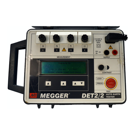
Features and Controls To electrode under test (Potential connection) To Potential test spike To electrode under test To Current test spike (Current connection) Charger socket ⁄ digit L.C.D. External 12 V d.c. supply Terminals Display contrast adjustment On / Off Test Button (Rotate clockwise to lock) Test control... -
Page 7: Initial Configuration
Initial Configuration Default Language Setting Select and set the default Frequency as follows: Select and set the display language default as follows: Using the centre k e y, scroll through the Press the left hand key and the TEST button Frequency options. -
Page 8: Setting Up Test Spikes
Setting up the Test spikes For earth electrode testing and for earth resistivity surveying, the instrument’s test leads are connected to spikes inserted in the ground. The way the connections are made depends on the type of test being undertaken and details are given in ‘... -
Page 9: Earth Testing Safety Precautions
‘Live’ earth safety precautions of which will cope with the maximum fault The DET2/2 allows earth testing to be done at a voltage and current. The isolation switch must relatively safe voltage using a maximum of a 50 V RMS be open whilst any personal contact is made square wave at a frequency of nominally 128 Hz. - Page 10 Earth Testing Safety Precautions If isolation switches cannot be used, the leads should be disconnected from the instrument before remote spikes and leads are handled. When the remote connections have been made, the final connections should be made to the instrument using insulated plugs, ensuring that the Operator takes adequate and appropriate precautions such as insulating mats, rubber gloves etc.
-
Page 11: Operation
Operation General Testing Procedure can be altered to achieve optimum conditions for the It is advisable that the battery of the D E T 2 / 2 is fully test. One or more of the following may be used:- charged before embarking on a test sequence. It can Test current Frequency be extremely inconvenient if the battery becomes too Using the right hand... -
Page 12: Display Messages
Operation resistance check of the of the Potential circuit. After a Display Messages short pause, the result of this check is displayed on the When appropriate, messages are displayed. The sub panel. If appropriate, the ‘P s p i k e‘ label then following message definitions are given: changes to ‘Retest’, giving the option to repeat the test “Please wait...”... -
Page 13: Error Messages
If These messages are displayed when the noise voltage an error message appears, switch the DET2/2 off, present is greater than the acceptable level, causing refer to ‘Repair and Wa r r a n t y’ and return the the measurement to be invalid. - Page 14 Operation unsuccessful, switch the DET2/2 off, refer to ’Repair and Wa r r a n t y’ and return the instrument to the manufacturer or approved agent, giving details of the error message and the software edition.
-
Page 15: Battery Charging
Battery Charging Battery capacity Disconnect and remove the test leads. The capacity of the battery is continuously monitored Connect the mains supply to the IEC 320 and displayed, adjacent to the battery symbol. The connector on the top right of the instrument. indicator segments will show fully charged, or recede Confirm that the message “C h a rging On”... - Page 16 Battery Charging Battery Charging Power cord plug Battery Charging Notes If the power cord plug is not suitable for your type of Do Not leave battery in a totally discharged state. socket, do not use an adaptor. You should use a If the instrument is idle for long periods, recharge suitable alternative power cord, or if necessary, change the battery at least every 6 months.
-
Page 17: Measuring Techniques
Measuring Techniques - Testing Earth Electrodes FALL-OF-POTENTIAL METHOD This is the basic method for measuring the resistance of earth electrode systems. However, it may only be practical on small, single earth electrodes because of limitation on the size of area available to perform the tests. -
Page 18: The 61,8% Rule
Measuring Techniques - Testing Earth Electrodes Fall-of-Potential Method with Short 'E' Lead THE 61,8% RULE Another way of making connections to the earth To obtain an accurate reading using the Fall-of- electrode is to connect to the earth electrode using only Potential method the current spike must be correctly one single connection to the ‘C1’... - Page 19 This is the 61,8% Rule and strictly applies only when medium size containing several rods, then these the earth electrode and Current and Potential spikes lie distances must be increased. The following table gives in a straight line, when the soil is homogeneous and a range of distances that agree with the rule.
-
Page 20: The Slope Method
Measuring Techniques - Testing Earth Electrodes THE SLOPE METHOD 'P2' terminal. The test spikes and the earth system This method is more applicable to larger earth should all be in a straight line. electrode systems or where the position of the centre of The ' C1' and 'P1' terminals are connected separately the earthing system is not known or inaccessible (e.g. - Page 21 Suppose the distance from the earth electrode system (ii) If it is necessary, further sets of test results can be to the current spike is EC. From the curve equivalent obtained with different values of E C, or diff e r e n t resistance readings to Potential positions 0,2EC, 0,4EC directions of the line of EC.
-
Page 22: Method Using 'Dead' Earth
Measuring Techniques - Testing Earth Electrodes METHOD USING A ‘DEAD’ EARTH The resistance of the two test leads can be found by The techniques using test spikes explained earlier are firmly joining their free ends together, pressing the Te s t the preferred methods of earth testing. -
Page 23: Bs7671 (16Th Edition Iee Wiring Regulations) Requirements
BS7671(16th Edition wiring regulations) Other Methods requirements There are other methods of earth electrode testing Regulation 713-11 of BS7671 specifies that the among which are the Four Potential, Intersecting Curves resistance of earth electrodes must be measured. The and Star Delta methods. M e gger Limited p u b l i c a t i o n s accompanying Guidance Notes describe a method of explain these test methods and give other helpful test that is very similar to the Fall-of-Potential method. -
Page 24: Determining 'Touch' Potential
Measuring Techniques - Testing Earth Electrodes Determining ‘Touch’ Potential ‘Touch’ potential is the potential difference a person would experience across his body if he were, for example, standing on the ground outside the earthed perimeter fence of a substation and touching the fence at the time a fault occurred. -
Page 25: Determining 'Step' Potential
Determining ‘Step’ potential ‘Step’ potential is the potential difference a person would experience between his feet as he walked across the ground in which a fault current was flowing. Firmly connect the instrument as follows :- Terminal 'C1' to the substation earth. Terminal ' C2' to the Current spike inserted in the ground some distance away. -
Page 26: Typical Variations In Soil Resistivity
Measuring Techniques - Measuring Soil Resistivity Typical variations in soil resistivity Because it is impossible to forecast the resistivity of the The resistance to earth of an earth electrode is soil with any degree of accuracy it is important to influenced by the resistivity of the surrounding soil. -
Page 27: Line Traverse
If the same line for the test spikes is maintained, but the separation of them is progressively widened, resistivity values at various depths can be obtained. By this means depth surveys may be made. More details can be found in the Megger Limited publications. See ‘Accessories‘. Calculation of resistivity Assuming that... - Page 28 Measuring Techniques - Measuring Soil Resistivity Resistivity calculation Nomogram...
-
Page 29: Continuity Testing
Measuring Techniques - Continuity Testing DET 2/2 can be used to measure metallic resistances of low inductance or capacitance. To test the continuity of conduit or other earth conductors the instrument can be connected as shown. Ensure that the circuit is de- energised, before connecting the instrument for measurement. -
Page 30: Specification
Specification 0,010 Ω to 19,99 kΩ (Auto-ranging) 1 mΩ resolution Earth Resistance Ranges: Accuracy (23°C ±2°C): ±0,5% of reading ±2 digits. Service error ±5% of reading ±2 digits ±10 mΩ (meets VDE service error over 50 mΩ) Test Frequency: 105 Hz to 160 Hz reversing d.c. (50 Hz environments default to 128 Hz, 60 Hz environments default to 150 Hz). - Page 31 Display: Alpha numeric LCD (130 mm x 35 mm) giving test information and a large (20 mm) 3 ⁄ digitLCD, maximum reading 1999 Instrument Protection: Meets the general requirements of IP54 Temperature Effect: <±0,1%/°C over the temperature range -10°C to +40°C Temperature Range: Operating: -10°C to +40 °C...
- Page 32 Specification Note: When the battery is charging, fast transients can cause the display to go blank. This will not normally affect the charging operation. (ii) External 12 V d.c. source Fuses (Non replaceable): Mains supply protection: 200 mA (T) ceramic HBC 20 mm x 5 mm to IEC 127/3 Battery protection: 2 A (T) ceramic HBC 20 mm x 5 mm to IEC 127/3 Battery in-line protection:...
- Page 33 Note: This table can only be used for readings from a Resistance value column is correct for resistance DET2/2. readings < 2 Ω. For the 2 Ω to 20 Ω column and the > 20 Ω column, the decimal point should be moved accordingly.
- Page 34 Specification Maximum Maximum Reading Maximum Maximum Reading Resistance Resistance < 2 Ω 2 Ω to 20 Ω > 20 Ω > 20 Ω < 2 Ω 2 Ω to 20 Ω Value Ω Value Ω 0,050 0,036 1,100 1,036 10,45 104,5 0,100 0,083...
-
Page 35: Accessories
Accessories SUPPLIED Part Number U.S. OPTIONS Cat. Number Standard Accessory kit 250579 User Guide 6171-428 Canvas case containing:- Battery charging Power cord 2 x 20 in rods, leads (25,50 &100 ft) OPTIONAL Deluxe Accessory kit 250581 Publications ‘Getting Down to Earth’ AVTM25-TA Padded case to hold instrument, 2 x 20 in rods, leads... -
Page 36: Chart For Use With Slope Method
Chart for use with the Slope Method Values of P t / EC for Values of µ µ 0.40 0.6432 0.6431 0.6429 0.6428 0.6426 0.6425 0.6423 0.6422 0.6420 0.642 0.41 0.6418 0.6417 0.6415 0.6414 0.6412 0.6411 0.641 0.6408 0.6407 0.6405 0.42 0.6404 0.6403... - Page 37 µ 0.64 0.6072 0.6071 0.6069 0.6068 0.6066 0.6064 0.6063 0.6061 0.606 0.6058 0.65 0.6056 0.6055 0.6053 0.6052 0.605 0.6048 0.6047 0.6045 0.6043 0.6042 0.66 0.604 0.6039 0.6037 0.6035 0.6034 0.6032 0.6031 0.6029 0.6027 0.6026 0.67 0.6024 0.6022 0.6021 0.6019 0.6017 0.6016 0.6014 0.6013...
- Page 38 Chart for use with the Slope Method (continued) µ 0.90 0.5618 0.5616 0.5614 0.5612 0.561 0.5608 0.5606 0.5604 0.5602 0.56 0.91 0.5598 0.5596 0.5595 0.5593 0.5591 0.5589 0.5587 0.5585 0.5583 0.5581 0.92 0.5579 0.5577 0.5575 0.5573 0.5571 0.5569 0.5567 0.5565 0.5563 0.5561 0.93...
- Page 39 µ 1.16 0.5046 0.5043 0.5041 0.5038 0.5036 0.5033 0.5031 0.5028 0.5025 0.5023 1.17 0.502 0.5018 0.5015 0.5013 0.501 0.5007 0.5005 0.5002 0.4997 1.18 0.4994 0.4992 0.4989 0.4987 0.4984 0.4981 0.4979 0.4976 0.4973 0.4971 1.19 0.4968 0.4965 0.4963 0.496 0.4957 0.4955 0.4952 0.4949 0.4947...
- Page 40 Chart for use with the Slope Method (continued) µ 1.42 0.4232 0.4228 0.4225 0.4221 0.4217 0.4213 0.4209 0.4205 0.4201 0.4197 1.43 0.4193 0.4189 0.4185 0.4181 0.4177 0.4173 0.4168 0.4164 0.416 0.4156 1.44 0.4152 0.4148 0.4144 0.414 0.4136 0.4131 0.4127 0.4123 0.4119 0.4115 1.45...
-
Page 41: Repair And Warranty
Megger instruments, using genuine Megger spare parts. suitably trained and qualified personnel. The protection is Consult the Appointed Distributor/Agent regarding spare... -
Page 43: Guide De L'utilisateur
D E T 2 / 2 Contrôleur de masse numérique Guide de l’utilisateur... - Page 44 Les fusibles de remplacement doivent être du type et de la puissance corrects. • Avant de charger la batterie du DET2/2 vérifier que le fusible d’alimentation correct est installé, et que • Les Avertissements et les Précautions doivent être lus et compris avant d’utiliser l’instrument. Ils doivent être observés pendant l’usage.
- Page 45 Table des matière User Guide p2 Gebrauchsanleitung Guía del usuario Av e rtissements relatifs à la sécurité Ta ble des matières Description générale A p p l i c a t i o n s Symboles utilisés sur cet instrument Caractéristiques et commandes Attention: Consultez les notes Configuration initiale...
-
Page 46: Description Générale
Description générale Le Megger D E T 2 / 2 est un instrument portable compact et sens inverse des aiguilles d’une montre et le relâcher. autonome destiné à mesurer la résistance des électrodes L’ a ffichage LCD peut être ajusté en tournant le bouton de de mise à... -
Page 47: A P P L I C A T I O N
Applications L’installation de systèmes de mise à la masse satisfaisants Entretien des systèmes de mise à la masse est un élément clé de l’alimentation électrique, de la Après leur installation, les systèmes de mise à la masse sécurité du câblage et de l’économie des installations. Elle doivent être vérifiés pour détecter tout changement de la a également une importance unique dans de nombreux résistance dans le temps, ou dans des conditions... -
Page 48: Caractéristiques Et Commandes
Caractéristiques et commandes Vers électrode à tester (connexion de potentiel) Vers piquet d’essai Vers électrode à tester Vers piquet d’essai de potentiel (connexion de courant) de courant Affichage LCD Prise de chargeur à 3 chiffres ⁄ Bornes d’alimentation 12V c.c. extérieure Réglage de contraste de l’affichage Bouton Test Marche/Arrêt... -
Page 49: Configuration Initiale 4
Configuration initiale Réglage du langage par défaut Sélectionnez et réglez la fréquence par défaut comme suit : Choisissez et réglez le langage d’affichage par défaut A l’aide de la touche centrale , faites défiler les comme suit : options de fréquence. Lorsque la fréquence requise est Appuyez simultanément sur la touche gauche s et sur mise en évidence par un cadre, appuyez sur la touche le bouton T E S T. -
Page 50: Mise En Place Des Piquets D'essai 5
Mise en place des piquets d’essai Pour les essais d’électrodes de mise à la masse et pour les études de résistivité du sol, les câbles d’essai de l’instrument sont connectés à des piquets enfoncés dans le sol. La façon dont les connexions sont réalisées est fonction du type d’essai entrepris, et les détails appropriés sont fournis à... -
Page 51: Précautions De Sécurité De Contrôle De Masse 5
Précautions de sécurité de contrôle de masse Isolement ou doublage des électrodes dépasser 1 kV. Les précautions de sécurité suivantes sont Il est préférable d’isoler l’électrode de mise à la masse à par conséquent essentielles. tester du circuit qu’elle protège avant d’effectuer l’essai, de Toutes les personnes mises en jeu doivent être manière à... - Page 52 Précautions de sécurité de contrôle de masse appropriées telles que des tapis isolants, des gants en caoutchouc, etc. I n t e r r u p t e u r d ’ i s o l e m e n t b i p o l a i r e Fuite à...
-
Page 53: Ajustements Des Conditions D'essai 5
Exploitation Procédures générales d’essai Fréquence du courant d’essai Il est conseillé de charger complètement la batterie du A l’aide des touches de droite, augmentez ou D E T 2 / 2 avant de commencer une séquence d’essai. Le diminuez la plage de fréquence du courant d’essai. Vo i r déchargement de la batterie au cours d’un essai en ’Configuration initiale’... -
Page 54: Messages De L'aff I C H A G
Exploitation Après une pause de courte durée, le résultat de cette Messages de l’affichage vérification est affiché dans le panneau secondaire. Si Divers messages sont affichés lorsqu’approprié, avec les approprié, la légende “Piquet P” se transforme en définitions suivantes: ”E s s u ye r” pour pouvoir répéter l’essai lorsque la position “Attendre SVP..“... -
Page 55: Messages D'erreur 5
supérieur au niveau acceptable, et rend la mesure invalide. renvoyer l’instrument au fabricant ou à un agent approuvé, La modification de la fréquence d’essai n’aura aucun eff e t en fournissant les détails du message d’erreur et l’indice dans ce cas. Si possible, éliminer la source du bruit, ou du logiciel. -
Page 56: Charge De La Batterie 5
Charge de la batterie Capacité de la batterie Retirer toutes connexions des prises d’alimentation La capacité de la batterie est continuellement surveillée et extérieure de 4 mm. a ffichée à côté du symbole de batterie. Les segments Débrancher et retirer les câbles d’essai. indicateurs signaleront batterie... - Page 57 Prise du cordon d’alimentation de charge de Notes relatives à la charge de la batterie batterie Ne jamais laisser la batterie à l’état totalement Si la prise du cordon d’alimentation ne convient pas à votre déchargé. Si l’instrument n’est pas utilisé pendant de type de prise femelle, ne pas utiliser d’adaptateur.
-
Page 58: Essai De Continuité 5
Essai de continuité METHODE DE CHUTE DE POTENTIEL C’est la méthode élémentaire de mesure de la résistance des systèmes d’électrodes de mise à la masse. Cependant, elle ne peut convenir que pour de petites électrodes simples à cause des limitations de superficie disponible pour effectuer les essais. -
Page 59: Spécification
Spécification 0,010 Ω à 19,99 kΩ (Gamme auto) résolution 1 mΩ Gamme de résistance de masse: Précision (23°C ±2°C): ±0,5% de la lecture ±2 chiffres. Erreur de service ±5% de la lecture ±2 chiffres ±10mΩ (répond à l‘ erruer de service VDE de plus de 50 mΩ) Fréquence d’essai: 105 Hz à... - Page 60 Spécification Affichage: LCD Alphanumerique (130 mm x 35 mm) donnant informations d’essai et un grand affichage (20 mm) LCD de 3 ⁄ chiffres, lecture maximum 1999 Protection de l’instrument: Répond aux exigences générales de IP54 Effet de température: <±0,1%/°C sur une plage de température de -10°C à +40°C Plage de température: Exploitation: -10°C à...
- Page 61 Pendant la charge de la batterie, des courants transitoires rapides peuvent causer l’extinction de l’affichage. Ceci n’affectera pas normalement la charge. (ii) Source extérieurer 12 V d.c. source Fuses (Non remplaçables): Protection de l’alimentation secteur:200 mA (T) céramique HBC 20 mm x 5 mm conforme à IEC 127/3 Protection de la batterie: 2 A (T) céramique HBC 20 mm x 5 mm conforme à...
- Page 62 Spécification La spécification VDE 0413, partie 7, stipule que ces trouvée à partir de la colonne de gauche. La lecture instructions doivent contenir un tableau ou un schéma maximale donnée par l’instrument est trouvée en lisant la indiquant la valeur maximum que l’instrument doit aff i c h e r valeur correspondante dans une des trois colonnes de dans certaines conditions.
- Page 63 Va l u e r Lecture maximale Va l u e r Lecture maximale m a x i mum de m a x i mum de < 2 Ω 2 Ω to 20 Ω > 20 Ω > 20 Ω <...
-
Page 64: A C C E S S O I R E
A c c e s s o i r e s FOURNIS REFERENCE Guide de l’utilisateur 6 1 7 1 - 4 2 8 Cordon d’alimentation de charge de batterie OPTIONNELS Kit d’essai de masse à quatre bornes 6310 - 755 constitué... -
Page 65: Réparations Et Garantie
être envoyé port payé a l’adresse appropriée. Megger utilisant des pièces d’origine Megger. Consultez le Un exemplaire de la facture et la note d’envoi doivent être distributeur désigné/agent officiel concernant la fourniture envoyé... -
Page 67: Gebrauchsanleitung
D E T 2 / 2 Digitaler Erdungsprüfer Gebrauchsanleitung... -
Page 68: Sicherheitshinweise
• Es dürfen ausschließlich Ersatzsicherungen der richtigen Stärke und Klasse verwendet werden. • Vor dem Laden des DET2/2 ist sicherzustellen, daß die Stromzufuhr durch eine passende Sicherung geschützt wird und der Spannungswählschalter richtig eingestellt ist. • Die Sicherheitshinweise und Warnungen müssen vor Gebrauch des Instruments gelesen und verstanden und beim Gebrauch beachtet werden. -
Page 69: Inhalt
Inhalt User Guide Guide de l’utilisateur p.43 Guía del usuario p.91 Sicherheitshinweise Inhalt Allgemeine Beschreibung Anwendungsmöglichkeiten Funktionen und Regler Eingangskonfiguration Anschluß der Prüfstäbe Sicherheitsvorkehrungen zur Erdungsprüfung Auf Diesem Gérat verwendete Symbole Betrieb Vo rs i cht: Bitte beiliegende Anmerkungen Allgemeines Prüfverfahren beachten. -
Page 70: Allgemeine Beschreibung
Allgemeine Beschreibung Megger D E T 2 / 2 ist ein in sich geschlossenes kompaktes gedreht und losgelassen. tragbares Instrument zur Messung des Widerstands von Die L C D-Anzeige läßt sich über die Konstrasttaste an die Erdungselektroden und für Durchgangsprüfungen mit vier jeweiligen Lichtbedingungen anpassen. -
Page 71: Anwendungsmöglichkeiten
Anwendungsmöglichkeiten Die Installation funktionsfähiger Erdungsvorrichtungen für weitere Elektroden und Kabel zum Erreichen des gehört zu den unverzichtbaren Bestandteilen von vorgeschriebenen Gestamtwiderstands S t r o m v e r s o r g u n g s - , Verkabelungs-und Installationsarbeiten. Erdungsvorrichtung vermeiden lassen. -
Page 72: Funktionen Und Regler
Funktionen und Regler Zur geprüften Elektrode (Potentialanschluß) Zum Prüfstab Zum Prüfstab für Potential Zur geprüften Elektrode für Stromstärke (Stromstärkenanschluß) Ladebuchse LCD mit 3 ⁄ Stellen Anschluß für externe 12 V- Stromversorgung Einstellung des Anzeigenkontrastes Prüftaste Ein/Aus (zum Feststellen im Uhrzeigersinn drehen) Schalter zur Prüfsteuerung... -
Page 73: Eingangskonfiguration
Eingangskonfiguration Einstellung der Standardsprache Für jeden Standardwert läßt sich Die Standardsprache der Anzeige läßt sich wie folgt Standardfrequenzbereich mit den Tasten w ä h l e n : Schritten von je 0,5 Hz von 105 bis auf 160 Hz erhöhen. Drücken Sie gleichzeitig die linke Taste und die Die Standardfrequenz wird wie folgt gewählt und... -
Page 74: Anschluß Der Prüfstäbe
Anschluß der Prüfstäbe Zur Prüfung der Erdungselektroden und des spezifischen nahe beieinander verlaufen. Erdungswiderstands werden die Prüfkabel des Gerätes an die Stäbe angeschlossen, die wiederum in den Boden gesteckt werden. Wie die Anschlüsse vorgenommen werden, hängt davon ab, welche Art von Prüfung durchgeführt werden soll. -
Page 75: Sicherheitsvorkehrungen Zur Erdungsprüfung
Sicherheitsvorkehrungen zur Erdungsprüfung Trennung oder Duplizierung der Elektrode 1. Alle Beteiligten müssen hinsichtlich der Isolierungs- und Damit nur die Erdung und nicht die gesamte Anlage Sicherheitsvorkehrungen für die betroffene Anlage geschult gemessen wird, muß die zu prüfende Erdungselektrode und kompetent sein. Es müssen eindeutige Anweisungen zunächst vom Stromkreis getrennt werden, den sie schützt. - Page 76 Sicherheitsvorkehrungen zur Erdungsprüfung Falls sich keine Trennschalter verwenden lassen, müssen die Kabel vor Berühren der externen Stäbe und Kabel vom Gerät getrennt werden. Wenn die externen Anschlüsse vorgenommen worden sind, müssen die Endanschlüsse am Gerät mit isolierten Steckern erfolgen, wobei der Bediener geeignete ausreichende...
-
Page 77: Allgemeines Prüfverfahren
B e t r i e b A l l gemeines Prüfverfahren Prüfbedingungen geändert werden, optimale Um zu vermeiden, daß die Batterie des D E T 2 / 2 mitten in Bedingungen zu erzielen. Verändern lassen sich die einer Prüfreihe zu schwach wird, empfiehlt es sich, sie vor folgenden Parameter: Beginn der Prüfarbeiten ganz aufzuladen. -
Page 78: Meldungen Im Display
B e t r i e b P r ü f s t a b - Po t e n t i a l der Boden befeuchtet oder die Stäbe tiefer in den Wählen Sie mit der mittleren Taste auf der linken Seite Boden geschoben werden). -
Page 79: Fehlermeldungen
Gerät bitte an den Hersteller oder eine autorisierte "S p a n nungs-Null zu Gro ß" Reparaturwerkstatt. Siehe ’Reparatur und Garantie’ . "S t rom-Null zu Groß " "S p a n nungklemmen Au s chlüsse Prüfe n" "F r e m d s p a n nungsbehaftete Stro m - N u l l" Diese Meldung erscheint, wenn die Anschlüsse für ’P 1’... - Page 80 B e t r i e b Reparaturwerkstatt. "Setup data retrieval erro r" Beim Einschalten des Gerätes werden normalerweise die Standarddaten für Sprache, Frequenz und Stromstärke aufgerufen. Wenn dies nicht möglich ist, wird beim Einschalten die obenstehende Meldung (auf Englisch) angezeigt.
-
Page 81: Laden Der Batterie
Laden der Batterie Batteriekapazität Prüfkabel trennen und entfernen. Die Kapazität der Batterie wird kontinuierlich überwacht und Netzkabel am Verbinder IEC 320 oben rechts am neben dem Batteriesymbol angezeigt. Die Teilstriche der Gerät anschließen. Prüfen, ob die Meldung Anzeige weisen auf eine voll geladene oder bei "L a d evo rgang läuft"... - Page 82 Laden der Batterie K a b e l s t e cker zum Batterieladen Hinweise zum Laden der Batterie Wenn sich der Kabelstecker nicht für Ihre Steckdose eignet, Entladen Sie die Batterie n i ch t vollständig. Wenn verwenden Sie keinen Adapter, sondern besorgen Sie sich das Gerät über längere Zeit nicht benutzt wird, ein passendes Ladekabel oder schneiden Sie ggf.
-
Page 83: Durchgangsprüfung
D u rch g a n g s p r ü f u n g PRÜFUNG ÜBER POT E N T I A L A B FA L L Hierbei handelt es sich um die grundlegende Methode zur Widerstandmessung bei Erdungselektrodenvorrichtungen. Die Methode eignet sich allerdings nur für kleine Elektroden mit einzelner Erdung, da für die Prüfung evtl. -
Page 84: Technische Daten
Technische Daten 0,010 Ω bis 19,99 kΩ (automatische Bereichsauswahl) 1 m Ω Auflösung E rd u n g sw i d e rs t a n d : Genaugkeit (23°C ±2°C): ±0,5% des angezeigten Wertes ±2 Stellen. Betriebsfehler ±5% des angezeigten ±2 Stellen ±10 mΩ... - Page 85 A n ze i ge : Alphanumerische LCD (130 mm x 35 mm) für Prüfinformationen und eine große (20mm) LCD mit 3 ⁄ Stellen für Werte bis 1999 S chutz des Instruments: Erfüllt die allgemeinen Vorgaben von IP54 Te m p e r a t u r b e d i n g t e <±0,1%/°C über dem Temperaturbereich -10°C bis +40°C A b w e i ch u n g : Te m p e r a t u r b e r e i ch :...
- Page 86 Technische Daten H i n w e i s : Beim Aufladen der Batterie wird auf der Anzeige aufgrund von Übergangsspannungen evtl. nichts dargestellt. Der Ladevorgang bleibt hiervon normalerweise unberührt. ( i i ) Externe 12 V DC-Stromquelle S i ch e r u n gen (nicht ausw e ch s e l b a r ) : N e t z s t r o m s i c h e r u n g : 200 mA (T) Keramik HBC 20 mm x 5 mm nach IEC 127/3 B a t t e r i e s i c h e r u n g :...
- Page 87 Nach VDE 0413, Teil 7 muß diese Gebrauchsanweisung Wenn der Höchstwiderstand bekannt ist, kann dieser We r t eine Tabelle oder ein Diagramm mit den Höchstwerten anhand der linken Spalte gefunden werden. Die enthalten, Instrument unter bestimmten Höchstanzeige des Instruments befindet sich je nach Höhe Bedingungen anzeigen muß.
- Page 88 Technische Daten M a x i m a l e r Maximal ange zeigter We rt M a x i m a l e r Maximal ange zeigter We rt W i d e rs t a n d s - W i d e rs t a n d s - <...
-
Page 89: Zubehör
Zubehör MITGELIEFERT TEIL NUMMER Gebrauchsanweisung 6171-428 Batterieladekabel SONDERAUSSTATTUNG Erdungsprüfsatz mit vier Anschlüssen 6310 - 755 Tragetasche mit: Gummihammer, 4 verzinkten Stahlstäben (12 mm Durchmesser x 450 mm lang); zwei Stabentfernern, 3 m (x 2), 30 m und 50 m Kabel mit Anschlüssen auf Kabeltrommeln. Kompakter Erdungsprüfsatz mit vier Anschlüssen 6210 - 161 Tragetasche mit: 4 einschiebbaren verzinkten... -
Page 90: Guía Del Usuario
Reparaturen und Garantie Das Instrument enthält statisch empfindliche Bauteile, Reparaturarbeiten und Ersatzteile weshalb die gedruckte Schaltung sorgfältig behandelt Wenden Sie sich zwecks Wartungsarbeiten an Megger - werden muß. Falls die Schutzvorrichtungen eines lnstrumenten entweder an: Instruments beschädigt worden sind, sollte es nicht... -
Page 91: Guía Del Usuario
D E T 2 / 2 Probador de Puesta a tierra digital Guía del usuario... -
Page 92: Avisos De Seguridad
· Los fusibles de repuesto deben ser del tamaño, tipo y capacidad correctos. · Antes de cargar las pilas del DET2/2 asegure que se incorpore el fusible de suministro correcto y que el selector de voltaje esté ajustado correctamente. ·... -
Page 93: Tabla De Materias
Tabla de materias User Guide p2 Gebrauchsanleitung s67 Guide de l‘utilisateur p43 Avisos de seguridad Tabla de materias Símbolos usados en el instrumento Descripción general Referirse a la guía del usuario. Aplicaciones Características y controles Equipo totalmente protegido por Configuración inicial aislamiento doble (Clase II). -
Page 94: Descripción General
Descripción general El Megger D E T 2 / 2 es un instrumento portátil, TEST se gira en sentido contrario a las agujas del reloj compacto y autónomo que ha sido diseñado para medir y se suelta. Para adaptarse a las condiciones de... -
Page 95: Aplicaciones
Después instalación, deberán hacerse del DET2/2 es la prueba de electrodos de puesta a comprobaciones en el sistema de conexión a tierra tierra, ya sea en forma de electrodos individuales, para asegurar que no haya un cambio significativo en múltiples, sistemas de malla y placas o regletas de la resistencia durante un período... -
Page 96: Características Y Controles
Características y controles Al electrodo bajo prueba (conexión de potencial) A la punta de prueba de potencial Al electrodo bajo prueba A la punta de prueba (conexión de corriente) de corriente Toma del cargador D i s p l ay cristal líquido de 3 ⁄... -
Page 97: Configuración Inicial
Configuración inicial Reglaje del idioma por defecto prueba puede incrementarse en pasos de 0,5 Hz de Seleccione y luego fije el idioma del display como 105 Hz a 160 Hz, usando las teclas sigue: Seleccione y fije la frecuencia por defecto como Pulse la tecla izquierda y el botón T E S T sigue:... -
Page 98: Fijación De Las Puntas De Prueba
Fijación de las puntas de prueba Para la prueba de electrodos de puesta a tierra y el estudio de resistividad a tierra, los conductores de prueba del instrumento se conectan a puntas insertadas en el suelo. El modo en que se hacen las conexiones depende del tipo de prueba realizada y los detalles se incluyen en ’Técnicas de medición’... -
Page 99: Precauciones De Seguridad De Prueba A Tierra
Precauciones de seguridad con tierras ‘energ i z a d a s ’ esterillas de goma. El DET2/2 permite realizar pruebas de puesta a tierra a un voltaje relativamente seguro usando un máximo de onda cuadrada de 50 V RMS a una frecuencia nominal de 128 Hz. - Page 100 Precauciones de seguridad de prueba a tierra Los bornes ’P2’ y ’C2’ deberán ser conectados a través de un interruptor de aislamiento bipolar capaz de resistir la corriente y el voltaje de fallo máximos. El interruptor de aislamiento deberá estar abierto mientras se hace cualquier contacto personal con puntas de prueba remotas o conductores de conexión, como por ejemplo cuando se cambia su posición.
-
Page 101: Funcionamiento
Funcionamiento Procedimiento de prueba general mensaje “Por favor espera ...”. Se aconseja que las pilas del D E T 2 / 2 e s t é n Ajustes de la condición de prueba completamente cargadas antes de iniciar la secuencia Si el mensaje en el display inferior indica que no es de prueba. -
Page 102: Mensajes Del Display
Funcionamiento ”Filtro no” y “Filtro si”. “ Filtro si” ayuda a reducir el resistencia de punta de corriente alta, el instrumento ‘ruido’ que afecta la lectura. El tiempo invertido en realizará automáticamente una medición con una realizar una medición aumenta considerablemente con precisión más baja. -
Page 103: Mensajes De Error
medición, o si el circuito de potencial está mayor profundidad). incorrectamente conectado. Otros mensajes del display Un alto nivel de interferencia u otro fallo del “Bornes de corriente en circuito abierto” instrumento podría causar la visualización de uno Esto significa que el flujo de corriente de prueba es cualquiera de los mensajes siguientes: bajo, dando a entender que existe una resistencia de >500 kΩ... - Page 104 Si los datos de calibración almacenados en el instrumento han sido recuperados incorrectamente, se visualiza (en inglés) el mensaje arriba ilustrado al hacer la conexión. Desconecte el DET2/2, consulte la sección ’Reparación y Garantía’ y devuelva el instrumento al fabricante o a su agente autorizado, incluyendo detalles del mensaje de error y la edición...
-
Page 105: Carga De Pilas
Carga de pilas Capacidad de las pilas Desconecte el interruptor de prueba TEST. La capacidad de las pilas es continuamente Retire las conexiones hechas a las tomas del supervisada y visualizada, adyacente al símbolo de las suministro externo de 4mm. pilas. - Page 106 Carga de pilas Enchufe del cable eléctrico de carga de pilas Notas sobre la carga de pilas Si el enchufe del cable eléctrico no es adecuado para No deje la pila totalmente descargada. Si el su tipo de toma, no use un adaptador. Deberá usar un instrumento permanece inactivo...
-
Page 107: Pruebas De Continuidad
Pruebas de continuidad Metodo por descenso de Po t e n c i a l Este es el método básico para medir la resistencia de los sistemas de electrodos de puesta a tierra. No obstante, puede que sólo sea práctico en electrodos de puesta a tierra sencillos de tamaño pequeño, debido a las limitaciones del área disponible para efectuar las p r u e b a s . -
Page 108: Especificaciones
Especificaciones 0,010 Ω à 19,99 kΩ (reglage de gamma automático) 1 mΩ resolución Gammas de resistencia a tierra: Precisión (23°C ±2°C): ±0,5% de lectura ±2 digitos. Error de servicio ±5% de lectura ±2 digitos ±10mΩ (satisface el error de servicio VDE en más de 50 mΩ) Frecuencia de prueba: 105 Hz a 160 Hz en inversión c.c. - Page 109 Display: LCD Alfanumérico (130 mm x 35 mm) que aporta información de prueba y una gran pantalla (20mm) de 3 ⁄ dígitos, lectura máxima 1999. Protección del instrumento: Satisface los requisitos generales de IP54. Efecto de la temperatura: <±0,1%/°C sobre la gama de temperaturas -10°C à +40°C Gama de temperaturas: Trabajo: -10°C à...
- Page 110 Especificaciones Nota: Durante la carga de las pilas, transitorias rápidas pueden poner en blanco el display. Esto no afectará normalmente el progreso de la carga. (ii) Fuente de 12 V c.c. externo Fusibles (no recambiables): Protección del suministro de la red: 200 mA (T) cerámica HBC 20 mm x 5 mm de acuerdo con IEC 127/3.
- Page 111 Para lecturas máximas Nota: Esta tabla sólo podrá usarse para lecturas de un superiores a 200Ω, use la columna de la derecha y DET2/2. ajuste la coma decimal según convenga. La tabla incluye la lectura máxima que sería permitida para un valor de resistencia máximo conocido,...
- Page 112 Especificaciones Valor de Lectura Máxima Valor de Lectura Máxima resistencia resistencia < 2 Ω 2 Ω to 20 Ω > 20 Ω > 20 Ω < 2 Ω 2 Ω to 20 Ω máximo Ω máximo Ω 0,050 0,036 1,100 1,036 10,45 104,5...
-
Page 113: Accesorios
Accesorios SUMINISTRADOS NUMERO DE PIEZA Guía del usuario 6171-428 Cable eléctrico de carga de pilas OPCIONALES Kit de puesta a tierra de cuatro bornes 6310 - 755 Comprende una bolsa portátil que contiene: martillo, 4 puntas de acero galvanizado, 12mm cuadrados por 450mm de largo, dos extractores de puntas, cables de 3m (2), 30m y 50m de largo con extremos rematados en sus carretes de enrollar. -
Page 114: Reparación Y Garantía
Reparación de Instrumentos y Piezas de Repuesto gastos, si procede, antes de empezar el trabajo en el Para un servicio de los instrumentos Megger contacte instrumento. por favor con:... - Page 116 This instrument is manufactured in the United Kingdom. The company reserves the right to change the specification or design without prior notice. Megger is a re g i s t e red trademark Part No. 6171-428 V10 Printed in England 0204...
Need help?
Do you have a question about the DET2/2 and is the answer not in the manual?
Questions and answers