Sign In
Upload
Manuals
Brands
Megger Manuals
Test Equipment
220015 Series
Megger 220015 Series Manuals
Manuals and User Guides for Megger 220015 Series. We have
1
Megger 220015 Series manual available for free PDF download: Manual
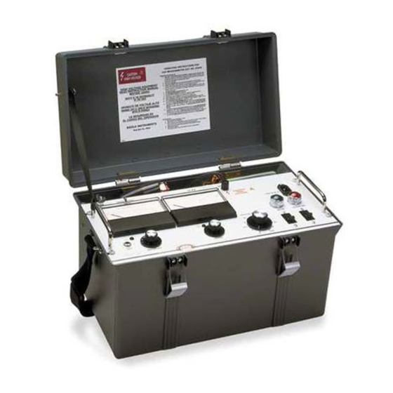
Megger 220015 Series Manual (84 pages)
15 kV DC Dielectric Test Set
Brand:
Megger
| Category:
Test Equipment
| Size: 3 MB
Table of Contents
Table of Contents
3
1 Introduction
7
Figure A: the Megger Catalog No. 220015 DC Dielectric Test Set
8
2 Safety Precautions
9
3 Receiving Instructions
13
4 Specifications
15
5 Description
21
General
21
Electrical
21
Power Supply Option
23
Overcurrent and Overvoltage Trip
24
Figure 1: Schematic Diagram of Catalog No. 220015
25
Figure 2: Schematic Diagram of Catalog No. 220015-50
26
Figure 3: Schematic Diagram of Catalog No. 220015-42
27
Figure 4: Schematic Diagram of Catalog No. 220015-43
28
Figure 5: Schematic Diagram of Catalog No. 220015-101
29
6 Control and Connector Identification
31
Figure 6A: Overall View of Catalog No. 220015
31
Figure 6B: Panel View of Catalog No. 220015
32
7 Setting up
33
Preparation
33
Selection of Location
33
Connections Procedure
34
Clearances
35
Power Supply Option, Catalog No. 220015-47
36
Figure 7: Testing in a Substation
37
Figure 8: Testing Parking Lot Lighting; the Test Set Shown Is Operating from an Inverter
38
Figure 9: Testing Transformer Terminals
39
Figure 10: DC Motor Test Setup
40
Figure 11: Generator Test Setup
40
8 Operation
41
Test Procedure
41
Breakdown of Test Item
42
Normal Shutdown Procedure
43
Interrupting a Test
43
9 Operation Notes
45
Line Voltage
45
Meter Range Settings During Transit
45
Stabilizing Switch
46
Stabilizing Switch (-50 Option)
46
Use of Guard
47
Voltage Control Scale
47
Use of Regulation Curve (-50 Option)
48
Step Voltage Testing
48
Fault Locating (Breakdown Testing)
48
External Current Meter
50
Figure 12: Regulation Curves with Stabilizer "Out", 120V Supply, -50 Option
50
Figure 13: Typical Guard Connection to Cable Pothead
51
Figure 14: Guard Connection for a Typical Cable Test
51
Figure 15: Typical Guard Connection for an Oil Circuit Breaker
52
Figure 16: Typical Guard Connection for Transformer Test
52
10 Application Notes
53
Theory of Insulation Testing
53
Applying the Test Set to Grounded Test Object
54
Three-Terminal Vs. Two-Terminal Tests
55
Measuring an Ungrounded Test Item
55
Figure 17: Two-Winding Transformer in Three-Terminal Form
56
Generalized Combined 2 and 3 Terminal Measurement
57
11 Routine Maintenance
59
Introduction
59
Inspection and Maintenance Procedure
59
12 Troubleshooting and Repair
63
General
63
Case Repairs
64
Repairs to Components of Chassis and Panel
64
Changing Line Voltage Tap (-47 Models Only)
65
Replacement of Output Cable W101
65
Replacement of Meters or Meter Amplifier Board
66
Replacement of Current Meter Range Circuit
66
Replacement of Voltmeter Range Circuit
66
Replacement of Stabilizing Switch S1
67
Replacement of Circuit Breakers
67
Replacement of Voltage Control Autotransformer T1
68
Replacement of the K2 Assembly
68
Replacement of Chassis-Mounted Assemblies
68
Replacement of Circuit Card U2
69
Calibration of Voltmeter
69
Calibration of Current Meter
70
Adjustment of R1 in Stabilization Network (-50 Option)
72
Catalog No. 220015-50
72
Catalog No. 220015-47,-50
73
Trouble Location Chart
74
Figure 18: Interior Views
76
Figure 19: Connections for Calibration of Voltmeter
77
Figure 20: Connections for Calibration of the Current Meter
77
13 Performance Check
79
14 Parts List
81
15 Warranty and Repairs
83
Warranty
83
Repairs
83
Advertisement
Advertisement
Related Products
Megger BITE 2P
Megger Easytest 20 kV
Megger SmartFuse 250
Megger Fault Sniffer 2
Megger MJOLNER 200
Megger Surgeflex 25
Megger 1003-062
Megger 1003-064
Megger 1003-066
Megger 1003-068
Megger Categories
Test Equipment
Measuring Instruments
Multimeter
Security Sensors
Portable Generator
More Megger Manuals
Login
Sign In
OR
Sign in with Facebook
Sign in with Google
Upload manual
Upload from disk
Upload from URL