Advertisement
Quick Links
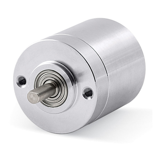
ROTAPULS
Incremental encoders
I28 • I40 • I41
Series
Warning: encoders having ordering code ending with "/Sxxx" may have mechanical and electrical characteristics different from standard and be supplied with additional documentation for special connections (Technical Info).
Attenzione: gli encoder con codice di ordinazione finale "/Sxxx" possono avere caratteristiche meccaniche ed elettriche diverse dallo standard ed essere provvisti di documentazione aggiuntiva per cablaggi speciali (Technical info).
Achtung: Geräte, deren Bestellschlüssel mit der Kennung /Sxxx enden, können in ihren mech. und elektr. Eigenschaften vom Standard abweichen. Sie werden daher mit einer ergänzenden Dokumentation ausgeliefert (Technical info).
Atención: los encoders con código de pedido acabado en "/Sxxx" pueden tener caracteristicas mecánicas y eléctricas diferentes a las basicas y documentación adicional relativa a conexiones especiales (Technical Info).
Attention: les encodeurs avec code de ordre terminant en "/Sxxx" peuvent avoir des caractéristiques mécaniques et électriques différentes du standard et documentation additionnelle pour les câblages spéciaux (Technical info).
EN
Mounting instructions
• Mount the flexible coupling 1 on the encoder shaft;
• fix the encoder to the flange 2 using screws 3, fix I40 model to the flange 2
using the supplied nut 4;
• secure the flange 2 to the motor (or to the mounting support);
• mount the flexible coupling 1 on the motor shaft;
• make sure the misalignment tolerances of the flexible coupling 2 are
respected.
ES
Instrucciones de montaje
• Montar el acoplamiento elástico 1 en el eje del encoder;
• fijar el encoder a la brida 2 mediante los tornillos previstos 3; para fijar el
encoder modelo I40 a la brida 2 utilizar la tuerca suministrada 4;
• fijar la brida 2 al motor (o al soporte);
• montar el acoplamiento elástico 1 en el eje del motor;
• asegurarse de que se respetan las tolerancias de desalineamiento del
acoplamiento elástico 1.
I28 – I41 [mm]
I41
I28
Signals
A
/A
Brown
Marrone
A, B, 0 outputs
Braun
-
(5 wires cable)
Marrón
Marron
EDE 9 pin
1
2
Yellow
Blue
A, /A, B, /B, 0, / 0
Giallo
Blu
outputs
Gelb
Blau
(8 wires cable)
Amarillo
Azul
Jaune
Bleu
Installation has to be carried out with power supply disconnected.
L'installazione deve essere eseguita in assenza di tensione.
Der Anschluss darf nur bei ausgeschalteter Versorgungsspannung erfolgen.
La instalación sólo debe ser efectuada en ausencia total de tensión.
Le montage du dispositif doit être effectué en
IT
• Montare il giunto elastico 1 sull'encoder;
• fissare l'encoder alla flangia di fissaggio 2 mediante le viti 3; per I40 fissare
l'encoder alla flangia 2 utilizzando il dado 4 in dotazione;
• fissare la flangia 2 al motore (o al supporto);
• montare il giunto elastico 1 sul motore;
• assicurarsi che le tolleranze di allineamento ammesse dal giunto elastico 1
siano rispettate.
FR
• Monter le joint élastique 1 sur l'arbre de l'encodeur;
• fixer l'encodeur au bride 2 au moyen des vis 3, fixer l'encodeur modèle I40
au bride 2 au moyen de l'écrou 4 fourni avec le dispositif;
• fixer le bride 2 au moteur (ou au support);
• monter le joint élastique 1 sur le moteur;
• s'assurer que les tolérances de mauvais alignement admises par le joint
élastique 1 soient respectées.
I41 with fixing clamps [mm]
Electrical connections
B
/B
0
/0
Blue
White
Blu
Bianco
Blau
-
Weiss
-
Azul
Blanco
Bleu
Blanc
3
4
5
6
Green
Orange
White
Grey
Verde
Arancione
Bianco
Grigio
Grün
Orange
Weiss
Grau
Verde
Anaranjado
Blanco
Gris
Vert
Orange
Blanc
Gris
absence totale de tension.
Istruzioni di montaggio
Instructions de montage
+VDC
0VDC
Shield
Red
Black
Shield
Rosso
Nero
Schermo
Rot
Schwarz
Schirm
Rojo
Negro
Malla
Rouge
Noir
Blindage
8
9
Case
Red
Black
Shield
Rosso
Nero
Schermo
Rot
Schwarz
Schirm
Rojo
Negro
Malla
Rouge
Noir
Blindage
DE
Montagehinweise
• Die Kupplung 1 auf den Geber montieren;
• Geber mit dem Adapterflansch 2 verschrauben; bei den Gebern der Serie I40
hierfür die mitgelieferte Überwurfmutter 4 benutzen;
• Den Adapterflansch 2 auf den Motor (oder auf den Trägen des Motors)
anschrauben;
• die Kupplung 1 auf die Motorwelle montieren;
• es muss sichergestellt sein, dass die zulässigen Toleranzen der Kupplung
eingehalten werden.
I40 [mm]
Connector type
male frontal side
maschio lato contatti
Aufsicht Stiftseite
macho lado contactos
mâle côté contacts
Cable
Wires not used must be cut at different
lengths and insulated singularly
EDE 9 pin
Advertisement

Subscribe to Our Youtube Channel
Related Manuals for Lika ROTAPULS I28 Series


Summary of Contents for Lika ROTAPULS I28 Series
- Page 1 ROTAPULS Incremental encoders I28 • I40 • I41 Series Warning: encoders having ordering code ending with "/Sxxx" may have mechanical and electrical characteristics different from standard and be supplied with additional documentation for special connections (Technical Info). Attenzione: gli encoder con codice di ordinazione finale “/Sxxx” possono avere caratteristiche meccaniche ed elettriche diverse dallo standard ed essere provvisti di documentazione aggiuntiva per cablaggi speciali (Technical info). Achtung: Geräte, deren Bestellschlüssel mit der Kennung /Sxxx enden, können in ihren mech.
- Page 2 • utiliser le dispositif tout en respectant les caractéristiques environnementales mentionnées par le constructeur. Lika Electronic reserves the right to make changes in specifications without prior notice – Lika si riserva il diritto di apportare modifiche senza preavviso - Die Fa. Lika Electronic behält sich das Recht zu Änderungen ohne Vorankündigung vor - Informaciones pueden ser modificadas por Lika Electronic sin preaviso –...
Need help?
Do you have a question about the ROTAPULS I28 Series and is the answer not in the manual?
Questions and answers