Table of Contents
Advertisement
Quick Links
7300 Series Sanitary End
Installation, Maintenance & Parts Manual
Featuring:
DORNER MFG. CORP.
P.O. Box 20 • 975 Cottonwood Ave.
Hartland, WI 53029-0020 USA
851-568 Rev. E
Drive Conveyors
For other service manuals visit our website at:
www.dorner.com/service_manuals.asp
Technology
INSIDE THE USA
TEL: 1-800-397-8664
FAX: 1-800-369-2440
OUTSIDE THE USA
TEL: 262-367-7600
FAX: 262-367-5827
Advertisement
Table of Contents

Subscribe to Our Youtube Channel
Related Manuals for Dorner AquaGard 7300 Series


Summary of Contents for Dorner AquaGard 7300 Series
- Page 1 7300 Series Sanitary End Drive Conveyors Installation, Maintenance & Parts Manual Featuring: Technology DORNER MFG. CORP. INSIDE THE USA OUTSIDE THE USA P.O. Box 20 • 975 Cottonwood Ave. TEL: 1-800-397-8664 TEL: 262-367-7600 Hartland, WI 53029-0020 USA FAX: 1-800-369-2440 FAX: 262-367-5827 For other service manuals visit our website at: www.dorner.com/service_manuals.asp...
-
Page 2: Table Of Contents
IMPORTANT 5174435, 6109427, 6685009 and corresponding patents and patent applications in other countries. Some illustrations may show guards Dorner reserves the right to make changes at any time removed. DO NOT operate equipment without notice or obligation. without guards. Dorner has convenient, pre−configured kits of Key Service Parts for all conveyor products. -
Page 3: Warnings - General Safety
A WARNING The safety alert symbol, black triangle with white exclamation, is used to alert you to potential personal injury hazards. Dorner cannot control the physical A DANGER installation and application of conveyors. Taking protective measures is the responsibility of the user. -
Page 4: Product Description
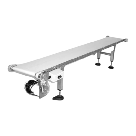
L= 18" (457 mm) ** For Heavy Load Bottom Mount Package, mount support under gearmotor. Figure 2 *** For conveyors longer than 12 ft (3658 mm), install support at frame joint. 7300 Series Sanitary End Drive Conveyors Dorner Mfg. Corp. 851-568 Rev. E... -
Page 5: Specifications
Maximum conveyor loads are based on: • Non-accumulating product • Product moving towards gearmotor • Conveyor being mounted horizontal • Conveyor being located in a dry environment • Conveyor with standard belt only 7300 Series Sanitary End Drive Conveyors 851-568 Rev. E Dorner Mfg. Corp. -
Page 6: Installation
Mounting Brackets” on page 7 and “Return Rollers” on page 8. Figure 3 Conveyors Longer Than 12 ft (3658 NOTE Dorner recommends cleaning all the “food Typical components (Figure 5). zones” prior to placing conveyor into service. Insure adequate access is provided for Conveyor frame extension... -
Page 7: Attaching Conveyor To Stands Or Mounting Brackets
Install conveyor belt. Refer to steps 1 through 3 under “Belt Installation for Conveyor without Gearmotor Mounting Package or Stands” on page 13. Tension conveyor belt. Refer to “Conveyor Belt Tensioning” on page 14. 7300 Series Sanitary End Drive Conveyors 851-568 Rev. E Dorner Mfg. Corp. -
Page 8: Return Rollers
Figure 13 drive spindles on 16–18 ft (4877–5486 mm) conveyors. Figure 13 On 8–18 ft (2338–5486 mm) conveyor, repeat step 3 as necessary for other return rollers. 7300 Series Sanitary End Drive Conveyors Dorner Mfg. Corp. 851-568 Rev. E... -
Page 9: 8" (203 Mm) Through 18" (457 Mm) Wide Flat Belt Conveyors
Attach return roller assembly (Figure 16, item AI) on conveyor (Z). Make sure return roller assembly is perpendicular with conveyor frame as shown. Tighten screws (Figure 15, item AH) to 80 in-lb (9 Nm). 7300 Series Sanitary End Drive Conveyors 851-568 Rev. E Dorner Mfg. Corp. -
Page 10: Preventive Maintenance And Adjustment
• Replace worn or damaged parts required level of hygiene can be maintained. Lubrication Use Dorner Belt Cleaner. Mild soap and water may also be used. Do not soak the belt. For /05 woven polyester and /06 black anti-static belts, use a Conveyor Bearings bristled brush to improve cleaning. -
Page 11: A - Belt Removal For Conveyor Without
Using a 3mm hex key wrench (Figure 21, item AQ), loosen two set screws (AR) on bearing and head plate assembly (AS). Figure 21 Figure 18 Figure 21 7300 Series Sanitary End Drive Conveyors 851-568 Rev. E Dorner Mfg. Corp. -
Page 12: B - Belt Removal For Conveyor With Stands And/Or Gearmotor Mounting Package
(Figure 25, item BB) and (Figure 26, item BB) underneath the gearmotor while changing the be Place a temporary support (Figure 25, item BB) and (Figure 26, item BB) under gearmotor mounting Figure 24 package. 7300 Series Sanitary End Drive Conveyors Dorner Mfg. Corp. 851-568 Rev. E... -
Page 13: A - Belt Installation For Conveyor Without
A – Belt Installation for Conveyor without Gearmotor Mounting Package or Stands Orient conveyor belt so the splice leading fingers (Figure 29, item BD) point in the direction of belt travel (BE). Figure 31 7300 Series Sanitary End Drive Conveyors 851-568 Rev. E Dorner Mfg. Corp. -
Page 14: B - Belt Installation For Conveyor With Gearmotor Mounting Package And/Or Stands
If the maximum take-up stroke is achieved, Mounting package, install bracket (Figure 25, item AZ). replace the conveyor belt. Tension belt. Refer to “Conveyor Belt Tensioning” on page 14. 7300 Series Sanitary End Drive Conveyors Dorner Mfg. Corp. 851-568 Rev. E... -
Page 15: Pulley Removal
(Figure 34, item BJ) and (Figure 35, item AU) are removed. Remove screw (BJ) from conveyor (Z) and cross support post (AV). Figure 34 Figure 36 Figure 34 7300 Series Sanitary End Drive Conveyors 851-568 Rev. E Dorner Mfg. Corp. -
Page 16: B − Idler Pulley Removal
(BR), hex pinion (BO), two spacers (BS) and tail removal from head plates (BN), see “Bearing assembly (AN) from conveyor (Z). Removal” on page 17. Figure 41 Figure 41 7300 Series Sanitary End Drive Conveyors Dorner Mfg. Corp. 851-568 Rev. E... -
Page 17: Bearing Replacement For Drive Or Idler Pulley
(Figure 34, item BJ) and (Figure 35, item AU). Tighten screws to 33 in–lb (3.7 Nm). Figure 44 Repeat steps 6, 7 and 8 for opposite side of idler spindle. 7300 Series Sanitary End Drive Conveyors 851-568 Rev. E Dorner Mfg. Corp. -
Page 18: B - Idler Pulley Installation
Install two bearing covers (Figure 42, item BT) on tail assembly (AN). 10. Install gearmotor mounting package. See accessory instructions. Figure 47 Position tail assembly (AN) and two spacers (BS) on conveyor (Z). 7300 Series Sanitary End Drive Conveyors Dorner Mfg. Corp. 851-568 Rev. E... -
Page 19: Notes
NOTES 7300 Series Sanitary End Drive Conveyors 851-568 Rev. E Dorner Mfg. Corp. -
Page 20: Service Parts
Service Parts NOTE For replacement parts other than those shown in this section, contact an authorized Dorner Service Center or the factory. Key Service Parts and Kits are identified by the Performance Parts Kits logo . Dorner recommends keeping these parts on hand. -
Page 21: Tension End Components
7, 8, 9, and 11) 4576WW Idler Spindle SS WW = Conveyor width ref.: 02, 03, 04, 05, 06, 08, 10, 12, 18 456058 Head Plate Tension LH 456041 Wedge-Lok® Clamp Block 7300 Series Sanitary End Drive Conveyors 851-568 Rev. E Dorner Mfg. Corp. -
Page 22: Conveyor Frame And Extension
8’ (2438mm) 4730WW−09060 17’ (5182mm) 4730WW−12660 4750WW 9’ (2743mm) 4730WW−10260 18’ (5486mm) 4730WW−13860 4750WW WW = Conveyor width ref.: 02, 03, 04, 05, 06, 08, 10, 12, 18 7300 Series Sanitary End Drive Conveyors Dorner Mfg. Corp. 851-568 Rev. E... -
Page 23: 21 1" (25Mm) Sanitary Bolt-On High Sides
7’ Right Hand 462137SSP (2134mm) Left Hand 462137SSP 8’ Right Hand 462154SSP 462144SSP (2438mm) Left Hand 462144SSP 462154SSP 9’ Right Hand 462155SSP 462144SSP (2743mm) Left Hand 462145SSP 462154SSP 7300 Series Sanitary End Drive Conveyors 851-568 Rev. E Dorner Mfg. Corp. -
Page 24: 22 2" (51Mm) Sanitary Bolt - On High Sides
Right Hand 462254SSP 462244SSP (2438mm) Left Hand 462244SSP 462254SSP 9’ Right Hand 462255SSP 462244SSP (2743mm) Left Hand 462245SSP 462254SSP 10’ Right Hand 462255SSP 462245SSP (3048mm) Left Hand 462245SSP 462255SSP 7300 Series Sanitary End Drive Conveyors Dorner Mfg. Corp. 851-568 Rev. E... -
Page 25: -23 Sanitary Fully Adjustable Uhmw Guide
462338 462337 Guide Mounting Rail 15’ (4572mm) 462338 462338 Guide Mounting Rail 16’ (4877mm) 462339 462338 Guide Mounting Rail 17’ (5182mm) 462339 462339 Guide Mounting Rail 18’ (5486mm) 7300 Series Sanitary End Drive Conveyors 851-568 Rev. E Dorner Mfg. Corp. -
Page 26: -24 Sanitary Adjustable Width Uhmw Guides
462338 462337 Guide Mounting Rail 15’ (4572mm) 462338 462338 Guide Mounting Rail 16’ (4877mm) 462339 462338 Guide Mounting Rail 17’ (5182mm) 462339 462339 Guide Mounting Rail 18’ (5486mm) 7300 Series Sanitary End Drive Conveyors Dorner Mfg. Corp. 851-568 Rev. E... -
Page 27: Sanitary 2" (51Mm) Through 6" (152Mm) Wide Flat And Cleated Belt Return Roller
Acorn Nut M4−0.70 4514WW Return Roller Assembly 4516WW Return Roller Guard WW = Conveyor width ref.: 08, 10, 12, 18 960435MSS Hex Head Cap Screw M4−0.70 x 35mm 7300 Series Sanitary End Drive Conveyors 851-568 Rev. E Dorner Mfg. Corp. -
Page 28: Conveyor Mounting Brackets
Mount Assembly – Flat Belt 450590 Stand/Conveyor Ear Mount Bracket 450591 Mount Assembly – Cleated Belt 960610MSS Hex Head Cap Screw M6–1.0 x 10mm 492564SS Clamp Plate – Flat Belt 7300 Series Sanitary End Drive Conveyors Dorner Mfg. Corp. 851-568 Rev. E... -
Page 29: Configuring Conveyor Belt Part Number
A, guide profile 01 and belt type /02 ft (610mm) long, shaft position A, and 6.59 in (167.4mm) (general purpose, fused finger) cleat spacing 72–030200/02V Belt 74–030200A0659V Belt 7300 Series Sanitary End Drive Conveyors 851-568 Rev. E Dorner Mfg. Corp. -
Page 30: Return Policy
RMA will automatically close 30 days after being issued. To get credit, items must be new and undamaged. There will be a return charge on all items returned for credit, where Dorner was not at fault. It is the customer’s responsibility to prevent damage during return shipping.
Need help?
Do you have a question about the AquaGard 7300 Series and is the answer not in the manual?
Questions and answers