
Related Manuals for York Altair Series


Summary of Contents for York Altair Series
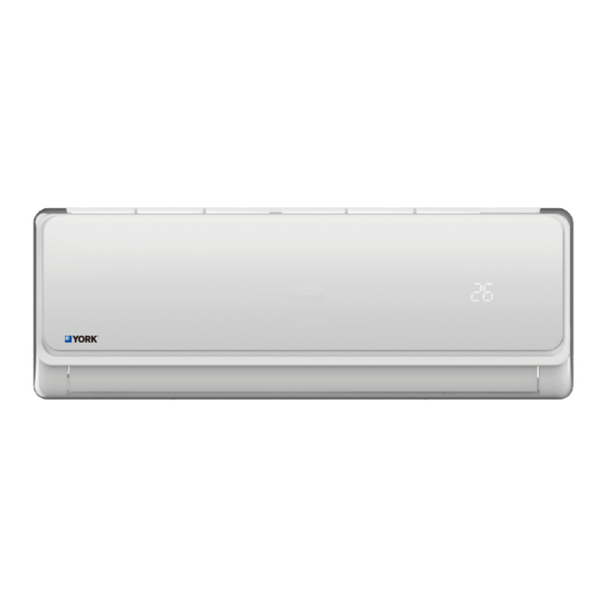
- Page 1 HIGH WALL INVERTER User's Manual New Released Form: UHKEALTAIR-171219 ALTAIR HIGH WALL INVERTER R-410A 60Hz 16SEER Issue Date Dec 19, 2017...
-
Page 2: Table Of Contents
CONTENTS Operation and maintenance Safety Precautions Notices for use Names of each part Clean and care Troubleshooting Installation service Notices for installation Packing list Indoor unit installation Outdoor unit installation Check after installation and test operation Note: All the pictures in this manual are just schematic diagrams, the actual is the standard. -
Page 3: Safety Precautions
Safety Precautions Incorrect installation or operation by not following these instructions may cause harm or damage to people, properties, etc. The seriousness is classified by the following indications: ! ! WARNING CAUTION This symbol indicates This symbol indicates the the possibility of death possibility of injury or or serious injury. - Page 4 Safety precautions The air conditioner Always switch off Take care not let must be grounded. the device and cut the remote control Incomplete ground- the power supply and the indoor unit ing may result in when the unit is not watered or being electric shocks.
- Page 5 Safety Precautions Don't install air Don't use liquid or Don't attempt to conditioner in a corrosive cleaning repair the air place where there is agent wipe the air conditioner by flammable gas or conditioner and yourself. liquid. The distance sprinkle water or between them other liquid either.
- Page 6 Safety Precautions This product contains fluorinated greenhouse gases. Refrigerant leakage contributes to climate change. Refrigerant with lower global warming potential (GWP) would contribute less to global warming than a refrigerant with higher GWP, if leaked to atmosphere. This appliance [ ]...
- Page 7 Safety Precautions ! CAUTION Don’t open the Don’t stand on the Don’t use the air windows and doors top of the outdoor conditioner for other for long time when unit or place heavy purposes, such as the air conditioner things on it. drying clothes, is running.
-
Page 8: Notices For Use
Notices for use The conditions of unit can t normally run * Within the temperature range provided in following table, the air conditioner may stop running and other anomalies may arise. > ℃ 43 (Apply to T1) Outdoor > ℃ Cooling 52 (Apply to T3) <... - Page 9 Notices for use Emergency operation * If the remote controller is lost or broken, use force switch button to operate the air conditioner. If this button is pushed with the unit OFF the air Force switch conditioner will operate in Auto mode. If this button is pushed with the unit ON, the air conditioner will stop running.
-
Page 10: Names Of Each Part
Names of each part Indoor unit Air inlet Force switch Air inlet grille Panel Power cable Air filter Pipe protection ring Air louver Air outlet Air vent Remote controller Outdoor unit Air inlet grille Air outlet Connection pipe Drain hose Air outlet Note: All the pictures in this manual are just schematic diagrams, the actual is the standard. -
Page 11: Clean And Care
Clean and care Warning Before the cleaning of the air conditioner, it must be shut down and the ● electricity must be cut off for more than 5 minutes, otherwise there might be the risk of electric shocks. Do not wet the air conditioner, which can cause an electric shock. Make ●... -
Page 12: Troubleshooting
Clean and care Clean the air filter ■ Mount the Filter 1. Reinstall the dried filter in reverse order of removal, then cover and lock the panel. Check before use 1. Check whether all the air inlets and outlets of the units are unblocked. 2. - Page 13 Troubleshooting Phenomenon Troubleshooting ● ● Has the power been shut down? Is the wiring loose? ● Air conditioner can Is voltage too high or too low ?(measured by professionals) ● not operate at all. Does it reach the set time for start up? ●...
-
Page 14: Notices For Installation
Notices for installation Important Notices ■ Before installating, please contact with local authorized maintenance center, if unit is not installed by the authorized maintenance center, the malfunction may not solved,due to discommodious contact. ■ The air conditioner must be installed by professionals according to the national wiring rules and this manual. - Page 15 Notices for installation Electrical Safety Requirements ● Be sure to use the rated voltage and air conditioners dedicated circuit for the power supply, and the power cord diameter must meet the national requirements. ≥ When the maximum current of air conditioner is 16A, it must use ●...
- Page 16 Notices for installation Requirements for operations at raised height ● When carrying out installation at 2m or higher above the base level, safety belts must be worn and ropes of sufficient strength be securely fasten to the outdoor unit, to prevent falling that could cause personal injury or death as well as property loss.
-
Page 17: Packing List
Packing list Packing list Packing list of the indoor unit Name Quantity Unit Indoor Unit Remote Controller Batteries 7# Instructions Drain hose Remoter controller holder Mounting board expansion screw Packing list of the outdoor unit Unit Name Quantity Outdoor Unit Connecting pipe Φ... -
Page 18: Indoor Unit Installation
Indoor unit installation Dimension drawing of indoor unit installation Space to the ceiling 15cm above Space to the wall Space to the wall 20cm above 20cm above 200cm above Space to the floor Mounting plate 1. The wall for installation of the indoor unit shall be hard and firm, so as to prevent vibration. - Page 19 Indoor unit installation Route of Pipeline 1. Depending on the position of the unit, the piping may be routed sideway from the left or the right ( Fig 1 ), or vertically from the back( Fig 2 )(depending on the pipe length of the indoor unit).
- Page 20 Indoor unit installation Fixing the Indoor Unit 1. Hang the indoor unit on the peg board, and move the unit from left to right to ensure that the hook is properly positioned in the peg board. 2. Push toward the lower left side and the upper right side of the unit toward the peg board, until the hook is embedded in the slot and makes a "click"...
-
Page 21: Outdoor Unit Installation
Outdoor unit installation Dimension drawing of outdoor unit installation Space to the obstruction Air in side Space to the obstruction Above Above Space to the obstruction Air out side Installation outdoor unit bolt Outdoor Unit Size of Shape A (mm) B (mm) W1(W2)*H*D) (mm) 665(710)×420×280... - Page 22 Outdoor unit installation Wiring Connection 1.Loosen the screws and remove E parts cover from the unit. 2.Connect the cables respectively to the corresponding terminals E parts cover of the terminal board of the outdoor unit (see the wiring diagram), and if there are signals connected to the plug, just conduct butt joint. 3.Ground wire: Remove the grounding screw out of the electric bracket, cover the grounding wire end onto the grounding screw and screw it into the grounding hole.
- Page 23 Outdoor unit installation Expelling the air ★ Outdoor unit refrigerant discharging method After the pipe side connection is complete, proceed as follows. Wait for Quickly tighten and Gas part 8 second connect the nut. Loosen the temporarily fastened The installing torque nut by half turn.
-
Page 24: Check After Installation And Test Operation
Check after installation and test operation Check after installation ★ Electrical Safety Check 1. If the supply voltage is as required. 2. If there is any faulty or miss connection in each of the power, signal and grounding wires. 3. If the grounding wire of the air conditioner is securely grounded. ★... - Page 25 Form: UHKEALTAIR-171219 2017 Johnson Controls, Inc. www.johnsoncontrols.com Johnson Controls reserve the right to change product features without prior notice.
Need help?
Do you have a question about the Altair Series and is the answer not in the manual?
Questions and answers
I am trying to find more information regarding an Altair unit installed in my cabin. The indoor unit is model number YHGE12ZJMAXA-RX. The outside unit appears to have failed on this 4 year old unit. The fan runs constantly but the compressor does not seem to engage. I have a technician scheduled to check it this week but he requested I provide any information available on the unit that might assist his diagnosis. We have no authorized York dealers in the service area. Could you reply with any warranty, diagnostic or technical manuals available? The exterior labels on the outside unit have become unreadable due to sun damage. Is there labeling inside that unit & if so, where? Finally. Is there a contact number could call with questions or to order parts? Thank you
Diagnostic and technical information available includes:
1. Error Codes:
- E1: Room temperature sensor fault
- E2: Outdoor unit-related issue (incomplete in the context)
2. Maintenance Checks:
- Ensure the drain pipe outlet is not blocked.
- Verify the ground wire is properly grounded.
- Check remote control battery installation and power.
- Inspect the outdoor unit's mounting bracket for damage.
3. Post-use Maintenance:
- Disconnect power and remove remote control batteries.
- Clean filters, unit body, and outdoor unit debris.
- Re-check outdoor unit mounting bracket for damage.
4. Installation Requirements:
- Avoid installation near flammable gases, strong electric/magnetic fields, high heat, noise, or in public passageways.
- Mounting structure must meet strength standards and be rustproof.
5. Service Advisory:
- Do not attempt self-repair; contact authorized service center.
This answer is automatically generated