
Subscribe to Our Youtube Channel
Related Manuals for AVANT 1300


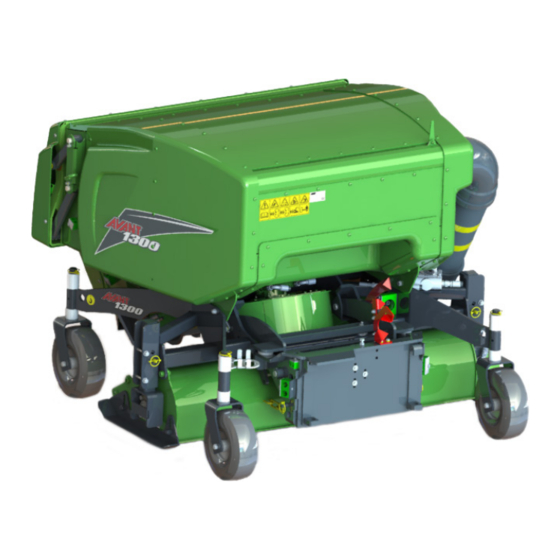
Summary of Contents for AVANT 1300
- Page 1 English Vacuum Brush 1300 2019 1 Operator's Manual for Attachment Vacuum Brush 1300 Product number: A428800 www.avanttecno.com A436675 2019 1 EN 2019-...
- Page 2 Vacuum Brush 1300 2019 1...
-
Page 3: Table Of Contents
Vacuum Brush 1300 2019 1 CONTENTS 1. FOREWORD ............................4 Warning symbols used in this manual ..........................5 2. DESIGNED PURPOSE OF USE ......................6 3. SAFETY INSTRUCTIONS FOR USING THE ATTACHMENT ............7 4. TECHNICAL SPECIFICATIONS ......................10 Safety labels and main components of the attachment ..................11 5. -
Page 4: Foreword
If you sell or transfer the equipment, be sure to hand over this manual to the new owner. If the manual is lost or damaged, you can request a new one from your Avant dealer or from the manufacturer. -
Page 5: Warning Symbols Used In This Manual
5 (40) Warning symbols used in this manual The following warning symbols are used throughout this manual. They indicate factors that must be taken into account to reduce the risk of personal injury or damage to property: WARNING SAFETY ALERT SYMBOL This symbol means: “Warning, be alert! Your safety is involved!”... -
Page 6: Designed Purpose Of Use
2. Designed purpose of use The AVANT Vacuum brush is an attachment that is suitable for use with AVANT multi purpose loaders that are shown in Table 1. The vacuum brush is intended for collecting of tree leaves or other light materials in parks, lawns, yards and similar areas. -
Page 7: Safety Instructions For Using The Attachment
Never lift or move an unlocked attachment. The Vacuum Brush 1300 is designed to be used by one operator at a time. Do not let WARNING others near the danger area of the equipment when it is in use. - Page 8 8 (40) Make sure that you use only an attachment that is in proper working condition. Perform daily inspections and read the instructions on service and maintenance. Never use the attachment if the hydraulic systems of the attachment and the loader are not completely in order.
- Page 9 9 (40) Remember to wear proper personal protective equipment: The noise level at the driver's seat may exceed 85 dB(A) depending on loader model and operating cycle. Extended exposure to loud noise can cause hearing impairment. Wear hearing protection while working with the loader. ...
-
Page 10: Technical Specifications
10 (40) 4. Technical specifications Table 2 - Vacuum Brush 1300 - Specifications Product number A428800 Working width: 1300 mm Floating: Avant Optifloat® Weight: 430 kg Collector box volume: 800 l Brush rotation speed: 0 rpm, 10...775 rpm Maximum input of hydraulic energy:... -
Page 11: Safety Labels And Main Components Of The Attachment
11 (40) 4.1 Safety labels and main components of the attachment Listed below are the labels and markings on the attachment. They must be visible and readable on the equipment. Replace any unclear or missing label. New labels are available via your retailer or contact information provided on the cover. - Page 12 Operate the attachment only from the driver’s seat. A431977 Attachment identification plate Table 4 - Vacuum Brush 1300 - Main components Avant quick coupling and OptiFloat® floating linkage Collector nozzle with rotating broom Brush rotating speed adjustment...
-
Page 13: Assembling The Attachment
Do not stay in the area between the attachment and the loader. Mount the attachment only on level surface. WARNING Never move or lift an attachment that has not been locked. Avant quick coupling system: Step 1: Lift the quick attach plate locking pins up and turn them backwards into the slot so that they are locked in the upper position. - Page 14 If your loader is not listed in Table 1 on page , ask your Avant dealer before using this attachment. The Vacuum brush is equipped with mechanical floating system OptiFloat®, which allows the attachment to move and tilt while it is placed on the ground.
-
Page 15: Connecting And Disconnecting Hydraulic Hoses
5.1 Connecting and disconnecting hydraulic hoses On Avant loaders the hydraulic hoses are connected using the multi connector system. If you have an Avant 300-700 series loader with the conventional quick couplers and wish to change to the multi connector system, contact your Avant dealer or service point for instructions or installation services. - Page 16 16 (40) Disconnecting hydraulic hoses: Before disconnecting the fittings, lower the attachment to safe position on solid and level surface. Turn the control lever of the auxiliary hydraulics to its neutral position. When uncoupling the attachment, always disconnect the hydraulic couplings before unlocking the quick coupling plate, to prevent hose damage and any oil spills.
-
Page 17: Instructions For Use
17 (40) 6. Instructions for use Check the attachment and the operating environment once more before starting to work, and that all obstacles have been removed from the operating area. Quick inspection of the equipment and the operating area before use are parts of ensuring safety and the best performance of the equipment. - Page 18 18 (40) Ensure that bystanders are at a safe distance when operating the equipment. Do not let anyone to enter danger area of the boom or to stay directly in front of the loader. Also make sure that it is safe to reverse with the loader.
-
Page 19: Using The Vacuum Brush
19 (40) 6.2 Using the Vacuum brush 19Set and adjust the Vacuum brush to correct operating position before starting the attachment. See the following chapters about floating system and adjustments. Starting the Vacuum brush: When the Vacuum brush is on the ground Move the auxiliary hydraulics control lever of the loader towards its locking position to start the Vacuum brush. - Page 20 20 (40) For the best collecting results, the 2-pump setting on the loader auxiliary hydraulics control and high engine rpm should be used. Adjust drive speed according to operating conditions. To prevent damaging the brush bristles, do not move the vacuum brush on a surface unless the brush is rotating.
-
Page 21: Working On Uneven Ground
21 (40) 6.3 Working on uneven ground Extra caution is needed when using the equipment on inclined terrains and slopes. Drive slowly especially on inclined, uneven, or slippery surfaces, and avoid sudden changes in speed or direction. Operate the controls of the loader with careful and smooth movements. -
Page 22: Transport Position
22 (40) 6.4 Transport position When driving with the loader, keep the Vacuum brush lifted off the ground and tilted back slightly. CAUTION Keep loader stable, transport the attachment as low and close to the ground as possible. Keep the telescopic boom retracted during drive. -
Page 23: Optifloat
23 (40) 6.6 OptiFloat® The attachment is equipped with a mechanical floating system, which enables efficient operation on uneven terrains. Floating refers to a linkage that allows the attachment to follow the contours of the ground surface without moving the loader boom. OptiFloat® allows the attachment to tilt sideways as well and eliminates the need for floating of the loader boom. -
Page 24: Safety Valve
24 (40) The red arrows show the correct initial position of the OptiFloat® system only, if the loader and Vacuum brush are at the same level and in straight position in relation to each other, in the direction of travel. 6.6.1 Safety valve For safety, the attachment is equipped with a valve that prevents using the attachment when it has been lifted... -
Page 25: Adjusting The Working Height
25 (40) 6.7 Adjusting the working height Normally, the bristles of the vacuum nozzle should touch the ground surface lightly. Suitable height setting depends on operating conditions and the material that is collected. The operating height of the Vacuum brush can be adjusted by using the plastic sleeves on the vertical axles of the bearing wheels. -
Page 26: Adjusting The Rotating Speed Of The Brush
26 (40) 6.8 Adjusting the rotating speed of the brush The vacuum brush is equipped with a valve for controlling the rotating speed of the brush steplessly. Adjusting the rotating speed is necessary when operating on sandy or fragile surfaces. Adjust the rotating speed when the brush is running to see the effect at once. -
Page 27: Emptying The Collector Box
27 (40) 6.9 Emptying the collector box Monitor the filling of the collector box while operating the Vacuum brush, and when it is about to fill, stop the brush to prevent blocking of the vacuum unit. Drive to the emptying site keeping the vacuum brush on the ground, or lifted just off the ground. -
Page 28: Handheld Vacuuming Tube (Optional Extra)
28 (40) 6.10 Handheld vacuuming tube (optional extra) Handheld vacuuming tube (A431787) is available as an option. With the flexible tube of the handheld vacuuming tube it is possible to collect leaves and waste in areas, which are otherwise hard to reach. When the tube is installed, the standard suction duct is blocked with a blocking plate that is included in the handheld vacuuming tube kit to direct the suction to the handheld tube in order to keep the suction effect strong enough. - Page 29 29 (40) Step 2 Remove the hatch (4) from the top of the vacuum unit. Step 3 Fasten the vacuuming tube (6) to the access on top of the vacuuming unit. Install the support bracket (7) of the vacuuming tube to the collector unit (8).
- Page 30 30 (40) Step 4 Before using the handheld vacuuming tube Block the conventional suction duct by turning the blocking plate (2) as indicated in the adjacent figure. The blocking plate (2) is locked in either position with stop lever (3). Open the shut-off valve that is located in the vacuuming tube.
-
Page 31: Removing A Blockage
31 (40) 6.11 Removing a blockage To avoid blockages it is important to keep the collector unit and the suction hoses clean. Especially wet tree leaves can get stuck on the walls, leading to building up of a blockage. If there are problems using the collector, try to use the vacuum brush briefly with the maximum rotating speed while not driving. -
Page 32: Maintenance And Service
Finding any fault means that the hydraulic hose or component must be replaced and the equipment must not be used until it is repaired. Spare parts are available from your nearest AVANT retailer or authorised service point. Leave the repair work to professional service technicians, if you don’t have adequate knowledge and experience about hydraulic assemblies and how to perform the repairing safely. -
Page 33: Cleaning The Attachment
Beware of the sharp shredding blades on the rotor. If the rotor remains out of balance after cleaning, it has probably been damaged. A damaged rotor must be repaired or replaced to prevent damage to the hydraulic motor. In this case, please contact the AVANT service. -
Page 34: Removing The Collector Box
34 (40) 7.2.2 Removing the collector box Remove the collector box as follows: 1. Lift the Vacuum brush slightly off the ground. 2. Open collector door completely using the auxiliary hydraulics of the loader. 3. Disconnect the discharge tube (1) from the box. -
Page 35: Checking And Sharpening The Shredding Blades
35 (40) 7.2.3 Checking and sharpening the shredding blades Blades that are in good condition will help to avoid blockages. The sharpened edges of the blade assembly A429325 are shown in adjacent figure and can be sharpened.. Do not sharpen the blades razor-sharp, as this can cause them wear quickly. -
Page 36: Lubrication
36 (40) 7.3 Lubrication On the Vacuum brush there are lubrication points at the vertical shafts of the wheels and at the bearing housing of the brush. Add a small amount of grease to these 1–2 times a year. Clean the end of the nipple before greasing and add only a small amount of grease at a time. -
Page 37: Warranty Terms
37 (40) 8. Warranty terms Avant Tecno Oy grants a warranty of one year (12 months) from the date of purchase for the attachment it manufactures. The warranty covers repair costs as follows: Work costs are covered, if the repair is not performed at the factory. - Page 38 SFS-EN ISO 12100, SFS-EN ISO 4413 Mallit / Modeller / Models Avant Hydraulitoiminen lehti-imuri; Avant-kuormaajan työlaite Hydraulisk lövsug; arbetsredskap för Avant lastare A428800 Hydraulic vacuum brush; attachment for Avant loaders 3.7.2019 Ylöjärvi, Finland Risto Käkelä, Toimitusjohtaja / Verkställande direktör / Managing Director...
Need help?
Do you have a question about the 1300 and is the answer not in the manual?
Questions and answers