
Related Manuals for AVANT Backhoe 210


Summary of Contents for AVANT Backhoe 210
- Page 1 English Backhoe 210 2020 1 Operator's Manual for Attachment Backhoe 210 Product number: A33747 www.avanttecno.com A440904 2020 1 EN 2016-...
- Page 2 Backhoe 210 2020 1...
-
Page 3: Table Of Contents
Backhoe 210 2020 1 CONTENTS 1. FOREWORD ............................4 Warning symbols used in this manual ..........................5 2. DESIGNED PURPOSE OF USE ......................6 3. SAFETY INSTRUCTIONS FOR USING THE ATTACHMENT ............7 4. TECHNICAL SPECIFICATIONS ......................10 Safety labels and main components of the attachment.................. 11 5. -
Page 4: Foreword
If you sell or transfer the equipment, be sure to hand over this manual to the new owner. If the manual is lost or damaged, you can request a new one from your Avant dealer or from the manufacturer. -
Page 5: Warning Symbols Used In This Manual
5 (32) Warning symbols used in this manual The following warning symbols are used throughout this manual. They indicate factors that must be taken into account to reduce the risk of personal injury or damage to property: WARNING SAFETY ALERT SYMBOL This symbol means: “Warning, be alert! Your safety is involved!”... -
Page 6: Designed Purpose Of Use
The backhoe must not be used for lifting of objects. The backhoe is not intended for dredging, it must not be immersed in water. The Backhoe 210 is not designed for any other use than specified in this manual and must not be used for any other purposes than what is intended for. -
Page 7: Safety Instructions For Using The Attachment
Never lift or move an unlocked attachment. The Backhoe 210 is designed to be used by one operator at a time. Do not let others WARNING near the danger area of the equipment when it is in use. - Page 8 8 (32) Operate only on well lit areas. If extra caution is required to avoid hitting dangerous or fragile materials in the ground, have another person nearby to spot possible buried items. Do not use the digger on horizontally tilted terrain. Ensure the stability of the loader WARNING and firmness of the ground also on even terrain.
- Page 9 9 (32) Make sure that the loader is equipped with necessary safety components, and that they are in working condition. Seat belt must be used. If there are specific hazards related to the operating area, use appropriate safety equipment. ...
-
Page 10: Technical Specifications
Maximum oil flow: 30 l/min Maximum hydraulic pressure: 20 MPa (200 bar) Suitable Avant loaders: See Table 1 Several available bucket options are listed in Table 5 on page 26. Contact your AVANT dealer for availability and for more information. -
Page 11: Safety Labels And Main Components Of The Attachment
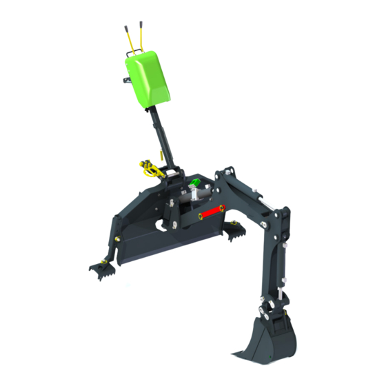
11 (32) 4.1 Safety labels and main components of the attachment Listed below are the labels and markings on the attachment. They must be visible and readable on the equipment. Replace any unclear or missing label. New labels are available via your retailer or contact information provided on the cover. - Page 12 Crushing hazard in the reach and swing area of the backhoe, keep bystanders away from danger area. A418372 Attachment identification plate Table 4 - Backhoe 210 - Main components Frame with Avant quick coupling brackets Top link (coupling bracket) Lifting boom Front boom (stick)
-
Page 13: Attaching The Attachment
5. Attaching the attachment The backhoe 210 is delivered with a 400 mm bucket fitted and it is ready for use as delivered. When coupling the backhoe onto the loader, in addition to the quick coupling and connecting the hydraulic fittings, the supporting bracket (also called the top link) must also be mounted. - Page 14 14 (32) Step 3: Lift the boom slightly – pull the boom control lever backward to raise the attachment off the ground. Turn the boom control lever left to turn the bottom section of the quick attach plate onto the attachment. ...
- Page 15 15 (32) Step 4: After locking pins positively locked, lock the support bracket (top link) Lift and tilt the backhoe so that the hole of the support aligns with the bracket on the loader boom Lock the support bracket with ...
-
Page 16: Connecting And Disconnecting Hydraulic Hoses
5.2 Connecting and disconnecting hydraulic hoses On Avant loaders the hydraulic hoses are connected using the multi connector system. If you have an Avant 300-700 series loader with the conventional quick couplers and wish to change to the multi connector system, contact your Avant dealer or service point for instructions or installation services. -
Page 17: Uncoupling And Storage
17 (32) Disconnecting hydraulic hoses: Before disconnecting the fittings, lower the attachment to safe position on solid and level surface. Turn the control lever of the auxiliary hydraulics to its neutral position. Risk of tipping over - Ensure stability of the equipment. Before disconnecting the hydraulic hoses, set the backhoe to a stable storage position, see page 17. -
Page 18: Removing The Backhoe From A Loader
18 (32) Risk of tipping over - Make sure the attachment is secured against any movement during storage. If necessary, use, for example, blocks of wood under the supports to ensure adequate stability. WARNING 5.3.1 Removing the backhoe from a loader 1. -
Page 19: Transport Position
19 (32) 5.3.3 Transport position Turn the backhoe to its middle position (straight forward) so that it will not affect the stability of the loader. If driving with the backhoe attached over longer distances or at high speed, lock the storage support on the boom. -
Page 20: Instructions For Use
20 (32) 6. Instructions for use Check the attachment and the operating environment once more before starting to work, and that all obstacles have been removed from the operating area. Quick inspection of the equipment and the operating area before use are parts of ensuring safety and the best performance of the equipment. -
Page 21: Checks Before Use
21 (32) 6.1 Checks before use Check that all obstacles, including any possibly hidden ones, have been removed from the working area or marked visibly before operation. Make sure that it safe to dig at the location. Find out if there are electric cables, water lines or similar ... -
Page 22: Outriggers
22 (32) 6.2.1 Outriggers The backhoe is equipped with outriggers, which stabilise the backhoe during use and especially when moving material to the sides. Risk of tipping over - Keep outriggers on ground. For stability, the backhoe must be lowered on the ground and the outriggers must be firmly on the ground when operating the backhoe. -
Page 23: Controls
23 (32) 6.2.2 Controls Move the auxiliary hydraulics control lever to its locking position when ready to start operating the backhoe. Release the auxiliary hydraulics control lever whenever not operating the backhoe. The lever should not be left to the locking position. Left control lever: Right control lever: ... - Page 24 24 (32) Planning and efficient use of the digging equipment Digging work is always started with thorough inspection of the site and planning the work in advance. Things to consider include at least the following: Inclinations and loader capabilities Digging movements and reach of the equipment ...
- Page 25 25 (32) The bucket should not be pressed too hard downwards, as it would cause the outriggers (and also the front tyres of the loader) to lift off the ground, pulling the loader towards the trench, and making digging ineffective. ...
-
Page 26: Operating On Inclined Terrain
Strike only gently, move the bucket to different position, if pins will not slide. 3. When attaching bucket, place the washers under the cotter pins. Table 5 - Backhoe 210 - Bucket options A415230 A35564 A415232 (standard bucket) Width: 250 mm 400 mm... -
Page 27: Maintenance And Service
Finding any fault means that the hydraulic hose or component must be replaced and the equipment must not be used until it is repaired. Spare parts are available from your nearest AVANT retailer or authorised service point. Leave the repair work to professional service technicians, if you don’t have adequate knowledge and... -
Page 28: Cleaning The Attachment
28 (32) 7.2 Cleaning the attachment Clean the attachment regularly to prevent accumulation of dirt which is more difficult to remove. A pressure washer and mild detergent can be used for cleaning. Do not use strong solvents, and do not spray directly at the hydraulic components, or at the labels on the attachment. -
Page 29: Warranty Terms
29 (32) 8. Warranty terms Avant Tecno Oy grants a warranty of one year (12 months) from the date of purchase for the attachment it manufactures. The warranty covers repair costs as follows: Work costs are covered, if the repair is not performed at the factory. - Page 30 2006/42/EC as amended). The following harmonized standards have been applied: SFS-EN ISO 12100, SFS-EN ISO 4413 Mallit / Modeller / Models Avant Hydraulitoiminen kaivuulaite; Avant-kuormaajan työlaite Hydraulisk grävaggregat; arbetsredskap för Avant lastare A33747 Hydraulic backhoe; attachment for Avant loaders 27.2.2020 Ylöjärvi, Finland Risto Käkelä, Toimitusjohtaja / Verkställande direktör /...
Need help?
Do you have a question about the Backhoe 210 and is the answer not in the manual?
Questions and answers