Advertisement
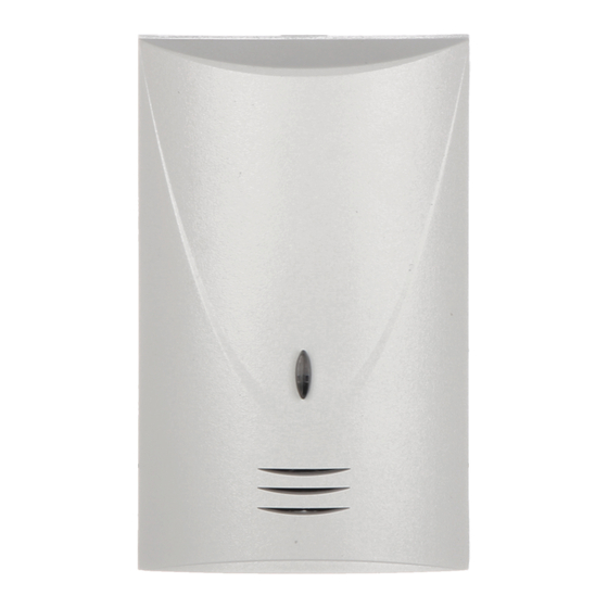
The INDIGO digital glass breaking detector can be used for detection of shattering of
ordinary, armored and/or laminated glass. The detector sounds an alarm upon recording
the occurrence of a low-frequency signal (impact sound) or a high-frequency signal
(sound of broken glass). The low-frequency sound wave caused by the impact makes
the detector analyze the high-frequency channel. The shock wave sound registered by
the microphone is signaled by blinking of the LED. The analysis of high-frequency chan-
nel lasts 4 seconds. If a high-
frequency sound, i.e. the glass
breaking sound, occurs during
that time, the detector will trip an
alarm.
TERMINALS:
COM - ground (0V)
12V
- supply input (9-16V
DC)
NC
- alarm relay (NC)
TMP
- tamper contact (NC)
Two pairs of pins are provided
for
setting
performance
rameters of the glass breaking
detector (see Table).
Normal mode
Test mode
LED indicator ON
LED indicator OFF
- pins open
state until a voltage of minimum 9V (±5%) is restored.
INSTALLATION
The detector is designed for indoor installation. It should be mounted directly on the wall
so that the protected glass surfaces are kept within the detector coverage area. It should
be borne in mind that all shades, curtains, furniture upholstery, soundproof tiles etc. will
reduce the detector range.
To install the detector, open the housing, remove the printed circuit board and make
suitable openings for cable entry and screws in the rear wall of the housing.
DIGITAL GLASS BREAK DETECTOR
®
jumpers for setting
operating parameters
pa-
The test mode is used for the functional check of
J3
J4
the detector. In this mode the detector will only
signal an alarm when a high-frequency sound is
recorded by the microphone.
The LED lights red when the detector is actu-
ated, which enables the installer to check the
detector for correct functioning.
The detector monitors the supply voltage. If the
voltage drops below 9V (±5%) for more than
- pins shorted
2 seconds, the detector will signalize a violation
INDIGO
NC NC TMP TMP COM+12V
alarm relay
tamper contact
J4
J3
Figure 1. View of INDIGO detector board
indigo_e 06/04
LED
microphon
high-frequency
channel
sensitivity control
+
SENS.
-
Advertisement
Table of Contents

Summary of Contents for Satel INDIGO
- Page 1 ® indigo_e 06/04 The INDIGO digital glass breaking detector can be used for detection of shattering of ordinary, armored and/or laminated glass. The detector sounds an alarm upon recording the occurrence of a low-frequency signal (impact sound) or a high-frequency signal (sound of broken glass).
- Page 2 Violation signaling time ....................2s Detection range ..................... up to 6m Operating temperature range................-10...+50°C Housing dimensions..................48x78x23mm Latest EC declaration of conformity and product approval certificates can be downloaded from our Web site www.satel.pl SATEL sp. z o.o. ul. Schuberta 79 80-172 Gdańsk POLAND tel.


Need help?
Do you have a question about the INDIGO and is the answer not in the manual?
Questions and answers