Advertisement
Quick Links
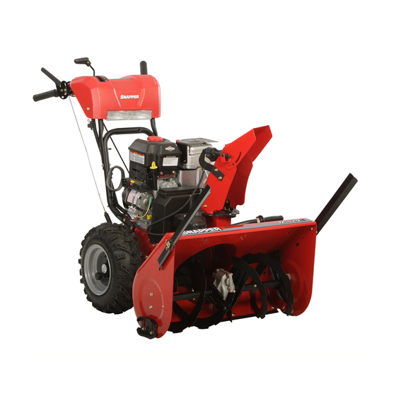
Setup Instructions
Model Nos.
1695734
1695906
1695735
1695908
1695909
1695820
1695964
1695843
1695986
1695853
EN
WARNING Failure to read and follow the operator's manual and all
operating instructions could result in death, serious injury, and/
or property damage.
FR
AVERTISSEMENT Le fait de ne pas lire et suivre le manuel de
l'opérateur et toutes les instructions peut entraîner la mort, des
blessures graves et/ou endommager des biens.
© Briggs & Stratton Corporation
1695987
1696004
1695988
1696005
1696001
1696006
1696002
1696007
1696003
1696025
Dual Stage Snowthrower
1696026
1696027
1696083
EN
NOTE: Where multiple variations of a unit are shown within a step (2A, 2B;
3A, 3B; etc.), determine which variation matches your unit and follow those
instructions.
FR
REMARQUE : Lorsque plusieurs variations d'un appareil sont présentées
au cours d'une étape (2A, 2B ; 3A, 3B ; etc.), déterminez celle qui correspond à
votre appareil et suivez ces instructions.
1752198 (Rev. B)
Advertisement

Related Manuals for Briggs & Stratton 1695734


Summary of Contents for Briggs & Stratton 1695734
- Page 1 Setup Instructions Model Nos. 1695734 1695906 1695987 1695735 1695908 1695988 1695909 1696001 1695820 1695964 1695843 1696002 1695986 1695853 1696003 WARNING Failure to read and follow the operator’s manual and all operating instructions could result in death, serious injury, and/ or property damage.
- Page 2 1/2” 1/2” Loosen upper fasteners. Remove lower fasteners. Carefully lift handle to the operating position while guiding the speed control rod over the tire. Make sure Z-fittings are secured in holes of control levers. Make sure cables are not caught between the upper and lower handle. Reinstall lower fasteners.
- Page 3 1/2” 7/16” Attach speed control rod to shift yoke and secure with lock washer and nut. Fixez la tige de commande de vitesse à la fourchette de boîte et sécurisez-la avec une rondelle frein et un écrou. 7/16 Move speed control lever to the full forward (6th gear) position. Attach upper and lower speed control rods using bolts and locknuts.
- Page 4 66 lb-in (7.6 Nm) 3/8” 7/16” Align slot in chute ring with arrow on mounting ring. Install fasteners and tighten securely, but do not overtighten. Install cable ties as shown. Alignez la fente dans l’anneau de l’éjecteur sur la flèche de l’anneau de montage.
- Page 5 “ 5/16 When facing chute opening, install a retainer on the right and back side of the chute ring. Tighten fasteners securely. Apply grease to the top and bottom surfaces of the mounting ring. Install chute making sure that the mounting ring is between the chute ring and retainers.
- Page 6 7/16” 66 lb-in (7.6 Nm) Align holes in chute ring with holes in chute as shown. Install fasteners and tighten securely, but do not overtighten. Connect wire harness. Alignez les orifices dans l’anneau de l’éjecteur sur les orifices dans l’éjecteur comme illustré. Installez les fixations et serrez fermement, mais sans excès.
- Page 7 Adjust the skid shoes so that the scraper bar has 1/8-3/16” clearance above a hard surface or 1” clearance above a gravel surface. Ajustez les sabots de patin pour que la barre du racloir ait un espacement de 1/8-3/16 po. au-dessus d’une surface dure ou de 1 po. au-dessus d’une surface gravelée.
-
Page 8: Safety System Test
Tires are over-inflated for shipping purposes. Check tire air pressure with an accurate gauge. The maximum pressure is stamped on the sidewall of the tires. WARNING • Do not inflate the tires above the maximum pressure. • Do not stand in front or over the tire assembly when inflating. Les pneus sont surgonflés pour faciliter l’expédition.