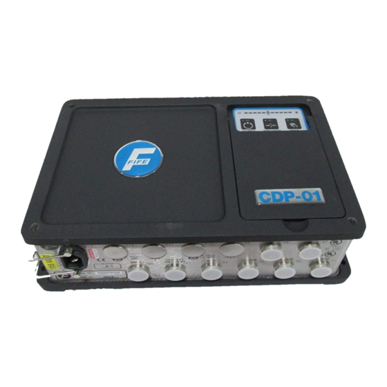
Fife CDP-01 Additional Instruction Manual
For sensor calibration using se-34 sensor
Hide thumbs
Also See for CDP-01:
- Additional instruction manual (24 pages) ,
- Additional instruction manual (22 pages) ,
- Additional instruction manual (19 pages)
Summary of Contents for Fife CDP-01
- Page 1 CDP-01 Additional Instruction Manual For Sensor Calibration Using SE-34 Sensor CDP-01 05-21-04 Figure Sheet 1-876...
- Page 2 CDP-01 05-21-04 Figure Sheet 1-876...
- Page 3 These additional instructions explain the special features of the system delivered to the customer. They are intended for being used in conjunction with the CDP-01 Reference Manual. The CDP-01 Reference Manual applies except as noted to the contrary in these instructions.
- Page 4 CDP-01 05-21-04 Figure Sheet 1-876...
-
Page 5: Table Of Contents
STANDARD ’O’ FRAME SE-34 (FIRST EDGE)..............2-1 STANDARD ’O’ FRAME SE-34 (SECOND EDGE)...............2-2 ’C’ FRAME SE-34 (FIRST EDGE) ..................2-3 ’C’ FRAME SE-34 (SECOND EDGE) ..................2-4 SPLIT SENSOR SE-34 (FIRST EDGE).................2-5 SPLIT SENSOR SE-34 (SECOND EDGE) ................2-6 CDP-01 05-21-04 Figure Sheet 1-876... - Page 6 CDP-01 05-21-04 Figure Sheet 1-876...
-
Page 7: General Introduction
A CDP-01 is required for this application. Software Part Numbers The software part numbers are located on the side of the CDP-01 housing. They include the Matrix Setup no. (MS), State Machine no. (SM) and firmware version ( Dx ). - Page 8 CDP-01 05-21-04 Figure Sheet 1-876...
-
Page 9: Sensor Calibration
The LED bar graph indicates contrast. If the contrast is too low an error message is displayed (left and right outer LEDs flash). Press the Automatic key to store the settings. Press the Manual key to abort the procedure. CDP-01 05-21-04 Figure Sheet 1-876... -
Page 10: Standard 'O' Frame Se-34 (Second Edge)
The LED bar graph indicates contrast. If the contrast is too low an error message is displayed (left and right outer LEDs flash). Press the Automatic key to store the settings. Press the Manual key to abort the procedure. CDP-01 05-21-04 Figure Sheet 1-876... -
Page 11: C' Frame Se-34 (First Edge)
The LED bar graph indicates contrast. If the contrast is too low an error message is displayed (left and right outer LEDs flash). Press the Automatic key to store the settings. Press the Manual key to abort the procedure. CDP-01 05-21-04 Figure Sheet 1-876... -
Page 12: C' Frame Se-34 (Second Edge)
The LED bar graph indicates contrast. If the contrast is too low an error message is displayed (left and right outer LEDs flash). Press the Automatic key to store the settings. Press the Manual key to abort the procedure. CDP-01 05-21-04 Figure Sheet 1-876... -
Page 13: Split Sensor Se-34 (First Edge)
Press the F1 key Check: LED 4 lit. Determine active portion of the Sensor by waving a flag in the sensor and watching the CDP-01 bargraph. Bring web material into sensor and fully cover the active portion of the sensor. -
Page 14: Split Sensor Se-34 (Second Edge)
The LED bar graph indicates contrast. If the contrast is too low an error message is displayed (left and right outer LEDs flash). Press the Automatic key to store the settings. Press the Manual key to abort the procedure. CDP-01 05-21-04 Figure Sheet 1-876...


Need help?
Do you have a question about the CDP-01 and is the answer not in the manual?
Questions and answers