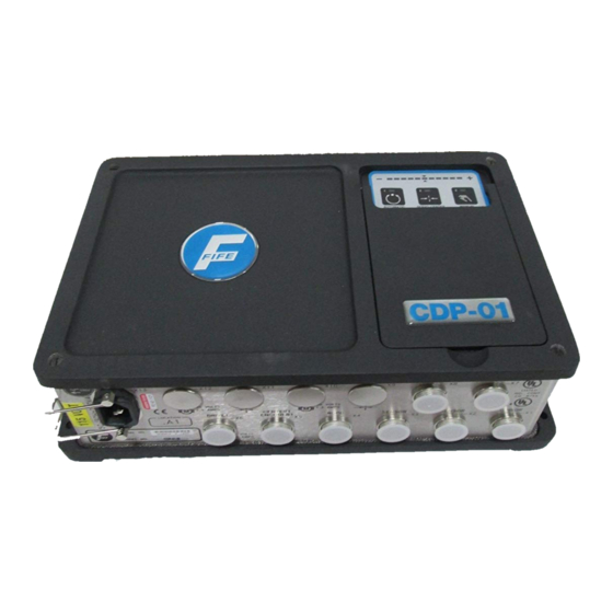
Fife CDP-01 Additional Instruction Manual
For using an sbpc-2x on a moving sensor centerguide with centerline shift
Hide thumbs
Also See for CDP-01:
- Additional instruction manual (24 pages) ,
- Additional instruction manual (14 pages) ,
- Additional instruction manual (18 pages)
Summary of Contents for Fife CDP-01
- Page 1 CDP-01 Additional Instruction Manual For Using an SBPC-2X on a Moving Sensor Centerguide With Centerline Shift CDP-01 12-14-04 Figure Sheet 1-879...
- Page 2 CDP-01 12-14-04 Figure Sheet 1-879...
- Page 3 These additional instructions explain the special features of the system delivered to the customer. They are intended for being used in conjunction with the CDP-01 Reference Manual. The CDP-01 Reference Manual applies except as noted to the contrary in these instructions.
- Page 4 CDP-01 12-14-04 Figure Sheet 1-879...
-
Page 5: Table Of Contents
SPECIAL FEATURES OF EXTERNAL CONTROL ............. 3-1 EXTERNAL CONTROL ....................... 3-2 CONTROL MATRIX......................3-3 EXPLANATION OF THE OPERATING MODES............3-4 to 3-10 SENSOR SELECTION – SENSOR INDICATOR............... 3-11 TROUBLESHOOTING FAULT DIAGNOSIS - FAULT RECTIFICATION..............4-1 CDP-01 12-14-04 Figure Sheet 1-879... - Page 6 CDP-01 12-14-04 Figure Sheet 1-879...
-
Page 7: General Introduction
A CDP-01-MMM with FifeNet firmware is required for this application. Software Part Numbers The software part numbers are located on the side of the CDP-01 housing. They include the Matrix Setup no. (MS) , State Machine no. (SM) and firmware version ( Dx ). - Page 8 CDP-01 12-14-04 Figure Sheet 1-879...
-
Page 9: System Calibration
9-2 ‘Defining Displacement Limts, Limiting Stroke’ on all drives. Adjusting Polarities and Gain The Polarities and Gain should be adjusted according to the ‘CDP-01 Reference Manual’ section 7-16 ‘Changing the System Gain with the Web at Standstill’ and section 7-16 ‘Changing the Guide Direction’. - Page 10 DRIVE 2 Sensor Seek for Left edge and Center guiding modes. Left edge guiding configuration. Center guiding configuration. DRIVE 3 Sensor Seek for Right edge and Center guiding modes. Right edge guiding configuration. Center guiding configuration. CDP-01 12-14-04 Figure Sheet 1-879...
-
Page 11: Overview Of Function
OVERVIEW OF FUNCTION Operator Control Options The CDP-01 signal amplifier can be operated by way of the CDP-01 control panel (internal operation) or via the SBPC-2X (external operation). The symbols below are used for the various operator control options in the following:... -
Page 12: External Control
The recommended use is to set the Value while the SM Command is zero (0). Then select the command with the SM Command. As soon as the CDP-01 receives the command signal, it will immediately send the command back on scheduled Data Word 11 (SM Command Feedback) for ‘hand shaking’. -
Page 13: Control Matrix
Left – Sensor positioner (D2) Right – Sensor positioner (D2) Left – Sensor positioner (D3) Right – Sensor positioner (D3) Sensor Selection – Edge Right Sensor Selection – Edge Left Sensor Selection – Edge Center CDP-01 12-14-04 Figure Sheet 1-879... -
Page 14: Explanation Of The Operating Modes
‘Left’ Press the - or + key to set ‘Left’ or ‘Right’ to manually alter the position of the drive. ‘Right’ Note: with External control, ‘Left-Rotating frame’ or ‘Right-Rotating frame’ mode must be set. CDP-01 12-14-04 Figure Sheet 1-879... -
Page 15: Manual - Sensor Positioner (D2) 0A
Press the - or + key to set ‘Left’ or ‘Right’ to manually alter the position of the drive. ‘Right’ Note: with External control, ‘Left - Sensor positioner (D3)’ or ‘Right - Sensor positioner (D3)’ mode must be set. CDP-01 12-14-04 Figure Sheet 1-879... -
Page 16: Automatic
‘Manual - Sensor positioner’ or ‘Servo-center’ modes. Left Edge Guiding Drive 1 – Edge Left Drive 2 – Line Center Right Edge Guiding Drive 1 – Edge Right Drive 3 – Line Edge Center Guiding Sensor configuration all three drives. CDP-01 12-14-04 Figure Sheet 1-879... - Page 17 The system adjusts the edge of the material web to the sensor position. Position the sensor with External control using the Guidepoint Shift command. The system gain (control sensitivity) of the rotating frame can be changed. CDP-01 12-14-04 Figure Sheet 1-879...
- Page 18 The system adjusts the edge of the material web to the sensor position. Position the sensor with External control using the Guidepoint command. The system gain (control sensitivity) of the rotating frame can be changed. CDP-01 12-14-04 Figure Sheet 1-879...
- Page 19 The rotating frame is switched to Manual. The panel is set to drive 1. AUTOMATIC – After Auto- Lock Set Automatic. ’Automatic’ The sensors search for the edge of the web, then move to the same position prior to ‘Auto-Lock’. CDP-01 12-14-04 Figure Sheet 1-879...
-
Page 20: Servo-Center
Press key 2 or select Servo-center. ’Servo - center’ The sensors move to their parked position. The rotating frame moves to the center position. Check: LED 2 lit. The sensor mode can be changed in this mode of operation. CDP-01 12-14-04 Figure Sheet 1-879... -
Page 21: Sensor Selection - Sensor Indicator
Left edge seek mode. DRIVE 1 Right edge guiding configuration. DRIVE 3 Right edge seek mode. DRIVES 1, 2 & 3 Center guiding configuration. DRIVE 2 Left edge guiding configuration. DRIVE 3 Right edge guiding configuration. CDP-01 12-14-04 Figure Sheet 1-879... - Page 22 CDP-01 12-14-04 Figure Sheet 1-879...
-
Page 23: Troubleshooting
SUPPLEMENTARY OPERATING MANUAL TROUBLESHOOTING An incorrect setting on the CDP-01 is often the cause for incorrect or unwanted guiding characteristics. Faults and the procedures for rectifying the faults are described in more detail in the CDP-01 Reference Manual, Chapter ‘Frequent Setting Errors’. Application-specific faults are explained below. - Page 24 CDP-01 12-14-04 Figure Sheet 1-879...


Need help?
Do you have a question about the CDP-01 and is the answer not in the manual?
Questions and answers