Fife CDP-01 Additional Instruction Manual
For side guide application
using se-34 sensor with width reference
for side guide width (variable ratio)
Hide thumbs
Also See for CDP-01:
- Additional instruction manual (24 pages) ,
- Additional instruction manual (18 pages) ,
- Additional instruction manual (14 pages)

Related Manuals for Fife CDP-01


Summary of Contents for Fife CDP-01
- Page 1 CDP-01 Additional Instruction Manual For Side Guide Application Using SE-34 Sensor With Width Reference For Side Guide Width (Variable Ratio) CDP-01 06-26-06 Figure Sheet 1-878-A © 2006 Fife Corporation. All rights reserved.
- Page 2 CDP-01 06-26-06 Figure Sheet 1-878-A © 2006 Fife Corporation. All rights reserved.
- Page 3 These additional instructions explain the special features of the system delivered to the customer. They are intended for being used in conjunction with the CDP-01 Reference Manual. The CDP-01 Reference Manual applies except as noted to the contrary in these instructions.
- Page 4 CDP-01 06-22-06 Figure Sheet 1-878-A...
-
Page 5: Table Of Contents
START UP / SE-34 STRIP WIDTH TO SIDE GUIDE WIDTH RATIO CALIBRATION ..2-9 START UP / SIDE GUIDE WIDTH DRIVE POLARITY ............2-10 START UP / GUIDE DRIVE POLARITY ................2-11 TROUBLESHOOTING FAULT DIAGNOSIS - FAULT RECTIFICATION............3-1 to 3-2 CDP-01 06-22-06 Figure Sheet 1-878-A... - Page 6 CDP-01 06-22-06 Figure Sheet 1-878-A...
-
Page 7: General Introduction
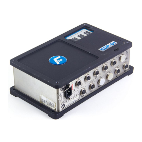
SE-34 width. A CDP-01-MHH is required for this application. Software Part Numbers The software part numbers are located on the side of the CDP-01 housing. They include the Matrix Setup no. (MS) , State Machine no. (SM) and firmware version ( Dx ). - Page 8 CDP-01 06-22-06 Figure Sheet 1-878-A...
-
Page 9: Overview Of Function
OVERVIEW OF FUNCTION Operator Control Options The CDP-01 signal amplifier can be operated by way of the CDP-01 control panel (internal operation) for setup purposes only. For normal operational control, the parallel port must be used. Control is to be supplied from a remote control panel or programmable logic controller. -
Page 10: Input Matrix - External Control
SUPPLEMENTARY OPERATING MANUAL Input Matrix - External Control Inputs CDP-01 Modes Auto Center Manual Jog Guide Right Jog Guide Left Auto Center Manual Jog Width In Jog Width Out L = Low level H = High level - = any... -
Page 11: Explanation Of The Operating Modes
The active drives are switched to Manual. Check: LED (3) lit. Setup functions can be performed. ‘Left’ Press the - or + key to set ‘Left’ or ‘Right’ to manually alter the position of the drive. ‘Right’ CDP-01 06-22-06 Figure Sheet 1-878-A... - Page 12 The guide point or system gain can be altered, if desired. Reference: CDP-01 Reference Manual, ‘Basic Settings’ section. AUTOMATIC – SIDE GUIDE Select ‘Automatic’ via external control for the Side Guide.
- Page 13 Select ‘Jog Guide Left’ or ‘Jog Guide Right’ via external control to manually alter the position of the mandrel. JOG WIDTH IN / OUT Select ‘Jog Width In’ or ‘Jog Width Out’ via external control to manually alter the position of the sensor. CDP-01 06-22-06 Figure Sheet 1-878-A...
-
Page 14: Start Up / Guide Position Transducer Calibration
The LED bar graph indicates contrast. If the contrast is too low an error message is displayed (left and right outer LEDs flash). Press the Automatic key to store the settings. Press the Manual key to abort the procedure. CDP-01 06-22-06 Figure Sheet 1-878-A... -
Page 15: Start Up / Side Guide Position Transducer Calibration
Press and hold the Left or Right Jog key to retract the Side Guide completely to its most wide position. Press the F2 key. Press the Automatic key to store the settings. Press the Manual key to abort the procedure. CDP-01 06-22-06 Figure Sheet 1-878-A... -
Page 16: Start Up / Se-34 Width Calibration
The LED bar graph indicates contrast. If the contrast is too low an error message is displayed (left and right outer LEDs flash). Press the Automatic key to store the settings. Press the Manual key to abort the procedure. CDP-01 06-22-06 Figure Sheet 1-878-A... -
Page 17: Start Up / Se-34 Strip Width To Side Guide Width Ratio Calibration
Note: If it is desired to abort this procedure, press and hold the Manual key until LED 5 turns off. The previous calibration is retained. When the calculations are complete (approximately 30 additional seconds), LED 5 will turn off. CDP-01 06-22-06 Figure Sheet 1-878-A... -
Page 18: Start Up / Side Guide Width Drive Polarity
Select ‘Servo Center’ mode. Verify that the Side Guide moves to the desired end for retract. If the Side Guide moves the wrong direction, select ‘Manual’ and change the Servo Center polarity. Reference: CDP-01 Reference Manual, Section “Servo Center Polarity”. Select ‘Automatic’ mode. Verify that the Side Guide moves to the edge of the strip. -
Page 19: Start Up / Guide Drive Polarity
Verify that the Guide moves to the center of the stroke. If the Guide moves to either end, select ‘Manual’ and change the Servo Center polarity. Reference: CDP-01 Reference Manual, Section “Servo Center Polarity”. Place the Drive in Automatic mode. Verify that the Guide follows the edge of the strip. - Page 20 CDP-01 06-22-06 Figure Sheet 1-878-A...
-
Page 21: Troubleshooting
SUPPLEMENTARY OPERATING MANUAL TROUBLESHOOTING An incorrect setting on the CDP-01 is often the cause for incorrect or unwanted guiding characteristics. Faults and the procedures for rectifying the faults are described in more detail in the CDP-01 Reference Manual, Chapter ‘Frequent Setting Errors’. Application-specific faults are explained below. - Page 22 Web at Standstill”. FIFE CORPORATION 222 W. Memorial Road, Oklahoma City, OK 73114-2317, USA / Post Office Box 26508, Oklahoma City, OK 73126-0508, USA Phone: 405.755.1600 / 800.639.3433 / Fax: 405.755.8425 / E-mail: fife@fife.com / Web: www.fife.com CDP-01 06-22-06...
Need help?
Do you have a question about the CDP-01 and is the answer not in the manual?
Questions and answers