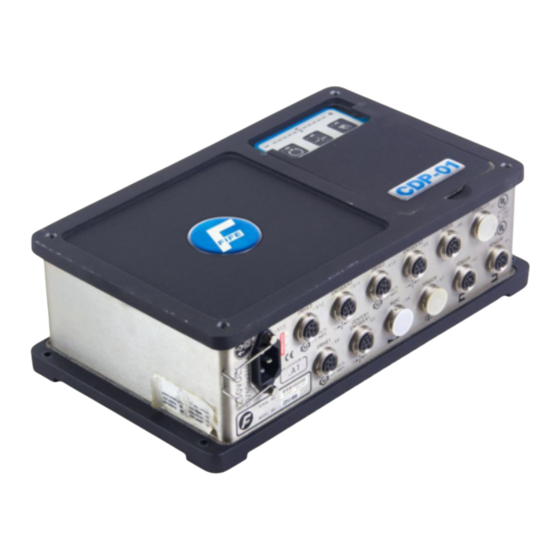
Fife CDP-01 Additional Instruction Manual
For centerguiding using two (2) dac-00x sensors
Hide thumbs
Also See for CDP-01:
- Additional instruction manual (24 pages) ,
- Additional instruction manual (22 pages) ,
- Additional instruction manual (14 pages)

Related Manuals for Fife CDP-01


Summary of Contents for Fife CDP-01
- Page 1 CDP-01 Additional Instruction Manual For Centerguiding Using Two (2) DAC-00X Sensors CDP-01 02-17-03 Figure Sheet 1-860...
- Page 2 CDP-01 02-17-03 Figure Sheet 1-860...
- Page 3 These additional instructions explain the special features of the system delivered to the customer. They are intended for being used in conjunction with the CDP-01 Reference Manual. The CDP-01 Reference Manual applies except as noted to the contrary in these instructions.
- Page 4 CDP-01 02-17-03 Figure Sheet 1-860...
-
Page 5: Table Of Contents
START UP / LEFT GUIDING SENSOR CALIBRATION ............2-5 START UP / RIGHT GUIDING SENSOR CALIBRATION.............2-6 START UP / SENSOR BANDWIDTH RATIO CALIBRATION ..........2-7 START UP / GUIDE POLARITY ....................2-8 TROUBLESHOOTING FAULT DIAGNOSIS - FAULT RECTIFICATION ..............3-1 CDP-01 02-17-03 Figure Sheet 1-860... - Page 6 CDP-01 02-17-03 Figure Sheet 1-860...
-
Page 7: General Introduction
2 sensors are not equal. Software Part Numbers The software part numbers are located on the side of the CDP-01 housing. They include the Matrix Setup no. (MS) , State Machine no. (SM) and firmware version ( Dx ). - Page 8 CDP-01 02-17-03 Figure Sheet 1-860...
-
Page 9: Overview Of Function
OVERVIEW OF FUNCTION Operator Control Options The CDP-01 signal amplifier can be operated by way of the CDP-01 control panel (internal operation) or remotely through the Parallel port (external operation). The symbols below are used for the various operator control options in the following:... -
Page 10: Input Matrix - External Control
SUPPLEMENTARY OPERATING MANUAL Input Matrix - External Control Inputs CDP-01 Modes External Lock Automatic Manual Servo Center Jog Left Jog Right L = Low level H = High level - = any CDP-01 02-17-03 Figure Sheet 1-860... -
Page 11: Explanation Of The Operating Modes
Press the - or + key to set ‘Left’ or ‘Right’ to manually alter the position of the drive. ‘Right’ JOG MANDREL LEFT / RIGHT Select ‘Jog Left’ or ‘Jog Right’ via external control to manually alter the position of the drive. CDP-01 02-17-03 Figure Sheet 1-860... - Page 12 The sensor mode must be pre-selected for Guiding. Press key 1 or Select ‘Automatic’ via external control. ’Automatic’ The guide point or system gain can be altered, if desired. Reference: CDP-01 Reference Manual, ‘Basic Settings’ section. SERVO CENTER Press key 2 or Select ‘Center Mandrel’ via external control.
-
Page 13: Start Up / Left Guiding Sensor Calibration
Press the F1 key. Bring web material fully into the sensor field of view. Press the F2 key. Press the Automatic key to store the settings. Press the Manual key to abort the procedure. CDP-01 02-17-03 Figure Sheet 1-860... -
Page 14: Start Up / Right Guiding Sensor Calibration
Press the F1 key. Bring web material fully into the sensor field of view. Press the F2 key. Press the Automatic key to store the settings. Press the Manual key to abort the procedure. CDP-01 02-17-03 Figure Sheet 1-860... -
Page 15: Start Up / Sensor Bandwidth Ratio Calibration
Note: If it is desired to abort this procedure, press and hold the Manual key until LED 5 turns off. The previous calibration is retained. When the calculations are complete (approximately 30 additional seconds), LED 5 will turn off. CDP-01 02-17-03 Figure Sheet 1-860... -
Page 16: Start Up / Guide Polarity
If the guide moves to either end, press the Manual key and change the Servo Center polarity. Reference: CDP-01 Reference Manual, Section “Servo Center Polarity”. Press the Sensor key repeatedly until LEDs 9 & 10 are lit. -
Page 17: Troubleshooting
Remedy: Select ‘Manual’ mode and change the polarity (guide direction) in EdgeR sensor mode (LED 10 lit) for drive 1 if using a CDP-01-MH or for drive 3 if using a CDP-01-MHH. Reference: CDP-01 Reference Manual, Section: “Changing The Guide Direction”... - Page 18 CDP-01 02-17-03 Figure Sheet 1-860...
Need help?
Do you have a question about the CDP-01 and is the answer not in the manual?
Questions and answers