
Related Manuals for Full Gauge Controls RCK-602 Plus


Summary of Contents for Full Gauge Controls RCK-602 Plus
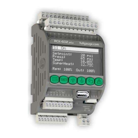
- Page 1 RCK-602 plus OLED Graphic Supervisory Hourmeter Alarms display system Progressive Suction Discharge Floating Preset Algorithm control control cooling system...
-
Page 2: Table Of Contents
1.SUMMARY 1. SUMMARY............................................2 2. DESCRIPTION..........................................4 3. APPLICATIONS..........................................4 4. GLOSSARY............................................4 5. TECHNICAL SPECIFICATIONS.......................................5 6. ELECTRICAL PRECAUTIONS......................................5 7. INSTALLATION OF RCK-602 plus.....................................6 8. DIMENSIONS...........................................6 9. CONNECTION SCHEMATIC......................................7 10. NAVIGATION KEYS........................................8 11. NAVIGATION TUTORIAL........................................9 12. SUMMARY SCREEN........................................10 12.1 GROUP SUMMARY SCREEN....................................10 12.2 SUCTION SUMMARY SCREEN....................................11 12.3 DISCHARGE SUMMARY SCREEN..................................12... - Page 3 1.SUMÁRIO 16. AUXILIARY FUNCTIONS......................................24 16.1 PUMP DOWN...........................................24 16.2 LIQUID INJECTION THERMOSTATS..................................25 16.3 ADIABATIC COOLING......................................25 16.3.1 CONTROL BY TEMPERATURE..................................25 16.3.2 CYCLICAL TIMER MODE....................................26 16.4 FLOATING COOLING......................................26 16.5 AUXILIARY PRESSOSTAT......................................27 17. ALARMS............................................28 17.1 VIEWING ALARMS........................................28 17.2 AUTOMATIC RESETS......................................29 17.3 OUTPUT SIGNALING......................................29 17.4 ALARM TABLES........................................30 17.4.1 SYSTEM ALARMS......................................30 17.4.2 SUCTION ALARMS......................................30 17.4.3 DISCHARGE ALARMS....................................30...
-
Page 4: Description
RCK-602 plus is a product dedicated to the control of condensing units and rack-type parallel compression systems by means of eight compressor or fan outputs divided into two analog outputs for proportional control and six digital relay outputs. -
Page 5: Technical Specifications
-The installation and maintenance of the product must be performed only by qualified personnel; ACCESSORIES: -Use only Full Gauge Controls original accessories; -If you have any questions, please contact our technical support. THROUGH CONTINUOUS DEVELOPMENT, FULL GAUGE CONTROLS RESERVES THE RIGHT TO CHANGE THIS MANUAL INFORMATION AT ANY TIME, WITHOUT PRIOR NOTICE. -
Page 6: Installation Of Rck-602 Plus
To remove the Controller from the DIN Rail, use a wrench compatible with the size of the lock as a lever. 8. DIMENSIONS For better mounting of the RCK-602 plus observe the dimensions of the product. 135,7 mm [5,34"] 110 mm [4,33'’] 3,21"... -
Page 7: Connection Schematic
9.CONNECTION SCHEMATIC Load feeling Screw torque = 0,5Nm 24Vac/dc Screw torque = 0,5Nm Screw torque = 0,2Nm Screw torque = 0,5Nm Supply voltage input Temperature sensor Pressure sensor Screw torque = 0,2Nm... -
Page 8: Navigation Keys
10.NAVIGATION KEYS RCK-602 plus has six navigation keys for the user to switch between screens, edit parameters, and view advanced functions, among other features: MENU UPPER LOWER BACK ALARM MENU key: Accesses the Main Menu and Control Menu. To access the Main Menu, you must be in the summary screens (Groups, Suction and Discharge) and hold the Menu key pressed for at least two seconds. -
Page 9: Navigation Tutorial
11.NAVIGATION TUTORIAL Gr1 DD/MM HH:MM:SS Upon power up, RCK-602 Suctions: plus displays the GROUPS #1 100.0 psi screen. This is the first summary #2 100.0 psi screen with information on the #3 100.0 psi controlled system. Discharges: #1 100.0 psi Using the UPPER and LOWER keys, you can browse the menu Gr1 DD/MM HH:MM:SS... -
Page 10: Summary Screen
12.1. Group summary screen: Displays the basic status of the lines (Suction and/or Discharge) that make up the group, if this is configured. By default, RCK-602 plus is configured with Suction 01 and Discharge 01 in Group 01. If the Group is not configured, go to Main menu Function settings Groups. -
Page 11: Suction Summary Screen
: Active alarm indication. Suc1: Suction 1; Suc2: Suction 2; : Percentage of power related to the outputs active in RCK-602 plus. Suc3: Suction 3. : Percentage of power required by the system related to the operating range. Control status indication:... -
Page 12: Discharge Summary Screen
Discharge 3. : Percentage of power related to the Temp : It is the value of the temperature sensor. outputs active in RCK-602 plus. : Percentage of power required by the Press : Is the pressure value read by system related to the operating range. -
Page 13: Continuation Of Summary Screens
12.SUMMARY SCREEN 12.4. Continuation of summary screens: Each suction and discharge has a summary screen where you can see how many outputs are associated and their respective status. After the equal sign, you can see how many percent of the compressor or fan is activated. You can even monitor the capacity control status (unloader valves and inverter output). -
Page 14: Individual Pressostat
12.SUMMARY SCREEN 12.5. Individual pressostat The individual pressostat screens are accessed from the Control Menu. To switch between available pressostat simply navigate using the Prs1 On Press:25.3 psi SP 1 SP 2 SP 3 10.0 20.0 30.0 SP 4 SP 5 SP 6 40.0 50.0... -
Page 15: Control Menu
Allows switching the system control on or off. When switched off, Sets the current date and time. This field is important RCK-602 plus only monitors the system but takes no action. for recording alarms and the logic that use the clock. -
Page 16: Suction Controls
The main control output is the first to be on and the last to be switched off. On the other hand, the auxiliary output is generally used to activate or deactivate an unloader valve to regulate the capacity of the compressor. RCK-602 plus has three activation... -
Page 17: Compressors With Proportional Modulation (Frequency Inverter)
When only digital outputs are associated to the Linear control mode, it commands the activation and deactivation of each compressor sequentially and with pressure intervals of the same magnitude (step). RCK-602 plus uses a pressure setpoint and hysteresis value for compressor suction control. If the compressors have unloader valves (auxiliary outputs), the drive logic is PPUU (Main first and then the unloader valves). -
Page 18: Linear Mode Using A Proportional Compressor (Inverter) In Conjunction With Compressors Associated With Digital Outputs
14.SUCTION CONTROLS Example: Linear control associated with digital outputs of compressors with unloaders Compressors with unloaders. When compressors with unloaders are used in linear mode, all the main compressor outputs are activated first and then the unloaders are used. 1.2.x.23 Modulation of compressor 2:0 I50 I 100 1.2.x.2 Control mode: Linear 1.2.x.24 Modulation of compressor 3: 0 I 33 I 66 I 100 1.2.x.3 Setpoint: 25 psi... -
Page 19: Linear Mode Associated With A Frequency Inverter
14.4.1.3 Linear Mode associated with a frequency inverter A 0-10 V analog output is used to control a frequency inverter linked to one or more fans. In this case RCK-602 plus considers the setpoint and hysteresis values of the analog output. The modulation of the analog output occurs when the difference between the measured pressure/temperature and the setpoint is equal to or greater than the minimum analog output value up to the maximum analog output value. -
Page 20: Rotation Mode
14.SUCTION CONTROLS Activation step = Hysteresis of digital outputs / Number of compressors = 12.0 / 3 = 4.0 psi Disregarding the dead band effect, the pressure values for the activation of compressors 1, 2 and 3 would be 34.0, 38.0 and 42.0 psi, respectively. Considering the dead band effect, no compressor must be activated until the pressure exceeds 45.0 psi, so compressors 1 to 3 will only be activated when the pressure exceeds this value. -
Page 21: Progressive Algorithm Mode
14.SUCTION CONTROLS 14.4.5 Progressive algorithm mode: The Progressive Algorithm control mode is ideal for systems that use compressors with different capacities for suction, which considers the capacity of each compressor to meet the system's thermal demand and seeks to optimize the use of unloader valves and minimize the number of compressors starts and stops. -
Page 22: Discharge Controls
Discharges can be controlled by monitoring pressure or temperature. The control type is adjusted according to the variable being used. Pressure: If the control type (1.3.x.3) is set for control by pressure, RCK-602 plus uses the pressure-related parameters 1.3.x.4 to 1.3.x.11, 1.3.x.20 and 1.3.x.21. -
Page 23: Fan With Inverter Modulation
15.DISCHARGE CONTROLS 15.2.1.3 Fan with inverter modulation: A fan with frequency inverter is controlled using an analog output (0-10 V). Only fan 01 of each discharge can be set as inverter. During operation, the inverter-modulated fan is the first to be activated and the last to be deactivated. Configuration example: In item 1.3.x.25 , set “Fan 01 Modulation”... -
Page 24: Auxiliary Functions
16.AUXILIARY FUNCTIONS RCK-602 plus allows configuring some additional functions to control the Rack system. The Pump Down logic and liquid injection thermostat logic apply to the suctions. The Pump Down function allows switching off all compressors of a group with refrigerant collection. The liquid injection thermostat, on the other hand, allows controlling the operating temperature of the compressors by means of a liquid injection valve. -
Page 25: Liquid Injection Thermostats
16.AUXILIARY FUNCTIONS 16.2 Liquid injection thermostats: The liquid injection thermostats can be used for compressor cooling. It is possible to associate one thermostat for each compressor. To enable a thermostat, it is necessary to configure a setpoint for the compressor working temperature, a hysteresis, a temperature sensor, and a digital output. The output is activated when the compressor temperature is higher than the setpoint plus the hysteresis and will be switched off when the temperature is lower than the setpoint. -
Page 26: Cyclical Timer Mode
If all four parameters are set correctly, the control will be done by both modes (temperature differential and temperature limits) and whenever at least RCK-602 plus one of the two modes has an activation condition, activates the adiabatic cooling control output. In this case, the output is activated when the dry bulb sensor temperature exceeds the Activation temperature and is deactivated when the temperature is lower than the Deactivation temperature;... -
Page 27: Auxiliary Pressostat
Safety value Alarm value 16.5 Auxiliary pressostat RCK-602 plus allows configuring up to three individual pressostat not linked to the main Rack control. Each pressostat can be associated with a pressure sensor and up to six digital outputs with independent setpoint and hysteresis. -
Page 28: Alarms
17.ALARMS RCK-602 plus features an alarm system in which alarms can be configured for protection or for display only. All alarm configurations are linked to the suction and discharge pressostat In the event of an alarm, an audible warning will sound and remain active until one of the following conditions occurs: - The alarm condition no longer exists and the alarm is not in manual reset condition. -
Page 29: Automatic Resets
If the number of attempts is set to the minimum value “Off ”, the reset will be manual only. If the number of attempts is set to the maximum value “Always”, RCK-602 plus will not limit the number of reset attempts, respecting only the times. -
Page 30: Alarm Tables
Manual reset record AL0003 Indication alarm Control functions locked Al0004 ECAL (Contact Full Gauge Controls) 17.4.2 Suction alarms: The letter x represents suctions 1, 2 and 3, where x is equal to 1, 2 and 3 respectively. Description Alarm Effect... -
Page 31: Individual Pressostat Alarms
17.ALARMS Description Alarm Effect Switches off all fans of the discharge pressostat. Low temperature AL0x04 Ignores the time between deactivations. Switches off all compressors of the suction pressostat in High temperature AL0x05 the same group, respecting the time between deactivation. Switches off all compressors of the suction pressostat, Critical high temperature AL0x06... -
Page 32: Main Menu
18.MAIN MENU To access the Main Menu, hold down the key for at least three seconds while navigating through the summary screens (Group, Suction, and Discharge). 1 Main Menu: 1 Function settings 2 System settings 3 Communication settings 4 Expansion settings 2.1 System: 5 Data management Unit of pressure... -
Page 33: Communication Settings
The cash dispenser terminal must be connected to the respective terminals of each instrument. 18.3 Data management: RCK-602 plus features a USB port that supports communication with a flash drive, which allows managing presets and updating the controller's firmware. 18.3.1 Export presets Controller Flash Drive: Allows copying a preset from the controller and store it on a flash drive. -
Page 34: Parameter Table
19.PARAMETER TABLE 1.1 Groups: Group-related settings menu. A group is a set of suction or discharge lines that are linked to each other (same refrigerant circuit). Example: A Rack refrigeration system with two suction lines, one for frozen goods and one for chilled goods, sharing the same discharge line forms a group consisting of three pressostat. - Page 35 19.PARAMETER TABLE 1.1.2 Number of suction pressostats: Defines the amount of suction pressostat to be controlled. 1.1.3 Number of discharge pressostats: Defines the amount of discharge pressostat to be controlled. 1.1.4 and 1.1.6 Suction x group : Associates suction pressostat with control groups. 1.1.7 / 1.1.9 and 1.1.11 Group x: Economy setpoint start time: Defines the time the setpoints of the pressostat belonging to group x will switch to economy mode.
- Page 36 19.PARAMETER TABLE Function Default Description Minimum Maximum Unit Compressor 1 principal output 1.2.x.35 Compressor 1 auxiliary output 1 1.2.x.36 Compressor 1 auxiliary output 2 1.2.x.37 Compressor 1 auxiliary output 3 1.2.x.38 1.2.x.39 Compressor 2 principal output Compressor 2 auxiliary output 1 1.2.x.40 Compressor 2 auxiliary output 2 1.2.x.41...
- Page 37 19.PARAMETER TABLE 1.2.x.3 Pressure setpoint: Pressure value for suction control where the system switches off all compressors. 1.2.x.4 Economy pressure setpoint: Alternative value for the pressure setpoint, usually higher than the pressure setpoint (1.2.x.3). 1.2.x.5 Digital output hysteresis: Pressure interval for controlling compressors associated with digital outputs. This pressure value is relative to the setpoint that defines the activation points of each compressor (activation interval = setpoint + hysteresis).
- Page 38 19.PARAMETER TABLE ON I OFF (0/100): On-off compressor that uses only one digital output (relay) to drive it. 0 I 50 I 100: Compressor that uses two digital outputs (relay) to drive it, the main output and an auxiliary output, where each output corresponds to 50% of the compressor capacity.
- Page 39 19.PARAMETER TABLE 1.2.x.64 Time between unloader deactivations: It is the time between deactivations of two auxiliary digital outputs (unloaders) of the same compressor. Example: A compressor with 0 | 33 | 66 | 100 modulation uses one main output and two auxiliary outputs. The time between deactivations of the two auxiliary outputs (66% and 100%) must be greater than the time between deactivations of the unloaders.
- Page 40 1.3.x.1 Refrigerant type: Allows selecting the refrigerant used in the discharge line. Note: If the discharge is from the same group as the suction, RCK-602 plus will consider the refrigerant configured in suction 1 regardless of the refrigerant defined in this parameter.
- Page 41 19.PARAMETER TABLE 1.3.x.12 Temperature setpoint: Temperature value for discharge control where the system switches off all fans. 1.3.x.13 Economic temperature setpoint: Alternative value for the temperature setpoint, usually higher than the pressure setpoint (1.3.x.13). 1.3.x.14 Digital output hysteresis: Temperature interval for controlling fans associated with digital outputs. This pressure value is relative to the setpoint that defines the activation points of each fan (activation interval = setpoint + hysteresis).
- Page 42 19.PARAMETER TABLE 1.3.x.27 to 1.3.x.32 Fan 1 to 6 digital output: Address of the digital output of fan 1 to 6. 0 = Not configured 1 = O1 2 = O2 3 = O3 4 = O4 5 = O5 6 = O6 1.3.x.33 Minimum time between activations: The function applies to the main control output of the fans and is the minimum time between two activations of the main digital output.
- Page 43 19.PARAMETER TABLE Function Description Default Minimum Maximum Unit -14,8 [off] (1,0) 850,0 (58,6) -14,8 [off] (1,0) Psi (Bar) 1.4.2.x.1 Low pressure alarm -14,7 (-1,0) 850,1 [off] (58,6) 850,1 [off] (58,6) Psi (Bar) High pressure alarm 1.4.2.x.2 Pressure alarm hysteresis 1,0 (0,1) 20,0 (1,4) 1,0 (0,1) Psi (Bar)
- Page 44 19.PARAMETER TABLE 1.4.3.x.5 Low Temperature alarm: The alarm is enabled when the temperature is higher than the configured value. 1.4.3.x.6 High Temperature alarm: The alarm is enabled when the temperature is higher than the configured value. 1.4.3.x.7 Critical high temperature alarm: The alarm is enabled when the temperature is higher than the configured value.
- Page 45 19.PARAMETER TABLE 1.4.5.x.2 Output function: Associates the alarm output with one of the following alarm events: 0 = Off 13 = Low superheating 14 = High superheating 1 = Any alarm 2 = Low pressure 15 = Any superheating alarm 16 = Low subcooling 3 = High pressure 4 = Critical high pressure...
- Page 46 19.PARAMETER TABLE 1.5.x.7 Cyclical timer active time: Time the compressor or fan remains on. 1.5.x.8 Cyclical timer deactive time: Time the compressor or fan remains off. 1.6 Auxiliary inputs: Allows configuring up to eight auxiliary inputs with specific functions. The letter “x” represents digital inputs 1 to 8. 1.6.1 Input x: Function Default...
- Page 47 19.PARAMETER TABLE 1.6.x.3 Type of contact NO-NC: Input polarity. NO is activated by a normally open contact and NC is activated by a normally closed contact. 1.6.x.4 Digital input address: Address of the physical digital input associated with this input. 0 = Not configured 5 = I2 1 = HI1...
- Page 48 19.PARAMETER TABLE 1.7.2.x Liquid injection thermostats: The letter x represents compressors 1 to 6 of each suction. Suction 1: x between 1 and 6. Suction 2: x between 7 and 12. Suction 3: x between 13 and 18. Function Description Minimum Maximum Default...
- Page 49 19.PARAMETER TABLE 1.7.3.x.2 Activation temperature: Dry bulb sensor temperature for the output to be activated. 1.7.3.x.3 Deactivation temperature: Dry bulb sensor temperature for the output to be deactivated. 1.7.3.x.4 Activation differential: Value of the difference between wet and dry bulb temperatures for the output to be activated. 1.7.3.x.5 Deactivation differential: Value of the difference between wet and dry bulb temperatures for the output to be deactivated.
- Page 50 19.PARAMETER TABLE 1.7.4.x.1 Fluctuation start temperature: Temperature value below which the discharge control setpoint starts to be reduced. 1.7.4.x.2 Minimum safety setpoint: Minimum value of the pressure setpoint for the discharge. 1.7.4.x.3 Safety subcooling: Minimum subcooling value. At this point the setpoint stops to be reduced. 1.7.4.x.4 Start time: Note: If parameters 1.7.4.x.4 and 1.7.4.x.5 are set to OFF, the adiabatic Time for the logic to start operating.
- Page 51 19.PARAMETER TABLE 1.7.5.x.1 Operation mode: Defines the operating mode as off, compression or decompression. 1.7.5.x.2 to 1.7.5.x.7 Pressure setpoint 01-06: Pressure setpoint of output 01-06. 1.7.5.x.8 to 1.7.5.x.13 Pressure hysteresis 01-06: Hysteresis of output 01-06. 1.7.5.x.14 Pressure sensor: Specifies the pressure sensor. Sensor options: 0 = Not configured 1 = S1...
- Page 52 19.PARAMETER TABLE 1.9 Sensors: Configurations related to sensors. 1.9.x Sensors S1-S6: The letter x represents sensor inputs S1 to S6. Function Description Minimum Maximum Default Unit Pressure at 4 mA Psi (Bar) 1.9.x.1 850,0 (58,6) Pressure at 20 mA 850,0 (58,6) 850,0 (58,6) Psi (Bar) 1.9.x.2...
- Page 53 19.PARAMETER TABLE 2. System settings Function Description Minimum Maximum Default Unit Unit of measurement for pressure Unit of measurement for temperature °F °C °C Language Spanish Portuguese Portuguese Audible warning (Buzzer) Display ECO mode enable 2.1 Unit of measurement for pressure: Unit of measurement used by the controller for temperature: Psi or Bar.
-
Page 54: Term Of Warranty
If in doubt, please contact Full Gauge Controls. Products manufactured by Full Gauge Controls, as of May 2005, have a two (02) year warranty, as of the date of the consigned sale, as stated on the invoice. They are guaranteed against manufacturing defects that make them unsuitable or inadequate for their intended use.
Need help?
Do you have a question about the RCK-602 Plus and is the answer not in the manual?
Questions and answers