Table of Contents
Advertisement
Quick Links
Have this manual in the palm of your
hand through the FG Finder app.
1. DESCRIPTION
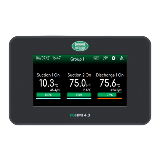
FG-HMI 4.3
The
is a digital display and configuration interface, compatible with
plus , version 2 or higher. It provides convenient and safe remote access to the settings of the
RCK-862 plus electronic controller.
FG-HMI 4.3
Whit the
users can remotely access controller information quickly and easily through
the color display and touchscreen interface. The interface is designed to be highly intuitive allowing
the user to access the controller's resources in a complete and simplified way. It also allows the
visualization and configuration of settings and sending commands to the controller.
FG-HMI 4.3
The
communicates with the electronic controller via an RS-485 connection. The touch
display has 4.3 inches, and settings can be adjusted for brightness and economy mode.
2. ELECTRICAL PRECAUTIONS
BEFORE INSTALLING THE CONTROLLER, WE RECOMMEND THAT YOU READ THE
ENTIRE INSTRUCTION MANUAL IN ORDER TO AVOID POSSIBLE DAMAGE TO THE
PRODUCT.
CAUTION WHEN INSTALLING THE PRODUCT:
-Before performing any procedure on this instrument, disconnect it from the power supply;
-Ensure that the instrument has proper ventilation, avoiding installing it on panels that contain
other devices that can cause it to operate outside the specified temperature limits;
-Install the product away from sources that may generate electromagnetic disturbances, such
as: motors, contactor, relays, electrovalves etc.
AUTHORIZED SERVICE:
-The installation or maintenance of the product must only be carried out by qualified
professionals.
ACCESSORIES:
-Use only original Full Gauge Controls accessories;
-If in doubt, contact technical support.
AS IT IS CONSTANTLY EVOLVING, FULL GAUGE CONTROLS RESERVES THE RIGHT TO
CHANGE THE INFORMATION CONTAINED IN THE MANUAL AT ANY TIME WITHOUT PRIOR
NOTICE.
3. APPLICATIONS
- Graphical interface for RCK-862 plus controller.
4. TECHNICAL SPECIFICATIONS
Power
Consumption
Controller operating temperature
Operating humidity
Pollution degree
Protection degree
USB Interface
Compatible with USB 2.0 Full-SpeedModule (USBFS)
RS-485 communication interface
Product Dimensions (WxHxD)
Cutout dimensions (mm)
5. STRUCTURE
84,7 mm
84,7 mm
3,33"
3,33"
2,6 mm
2,5 mm
0,1"
0,1"
6. COMPONENTS
The following components are included in the scope of delivery of
FG-HMI 4.3
Ÿ
digital interface;
Ÿ
Clamps and fastening screws;
Ÿ
Instruction manual;
Ÿ
Full Gauge adhesive;
Ÿ
Connectors.
FG-HMI 4.3
DIGITAL DISPLAY AND CONFIGURATION INTERFACE COMPATIBLE WITH
RCK-862 plus
THE
colors
Touch
Color
Economy
display
mode
screen
RCK-862
24Vac 50/60Hz ou 24Vdc ± 10%
32 to 122°F
10 to 90% RH (without condensation)
Standard Data Format for Thumbdrives: FAT32
Maximum Thumbdrive Size: 32GB
RS-485 Isolated
93,6 x 145,6 x 36,6 mm (3,68" x 5,73" x 1,44")
138 x 86 mm (5,43" x 3,38")
93,6 mm
93,6 mm
145,6 mm
145,6 mm
5,73"
5,73"
136,7 mm
136,7 mm
5,38"
5,38"
36,6 mm
34 mm
1,44"
FG-HMI 4.3
:
RCK-862
plus
ELECTRONIC CONTROLLER
RS
485
Serial
USB
Alarm
Alarms
communication
sound
7. WIRING DIAGRAM
Type 2 connector
RS-485
1
2
3
Communication
Type 1 connector: For Type 1 (5.0mm) connectors use a #1 Phillips screwdriver or 3.0mm
Screwdriver. Do not exceed the maximum torque of 0.5 Nm.
Type 2 connector: For Type 2 (3.5mm) connectors use #0 Phillips screwdriver or 2.4mm Slit. Do not
exceed the maximum torque of 0.2 Nm.
Cable: The maximum cable length is 1000 meters. The minimum specification of the cable should be
24AWG braided, in order to protect the communication line from outside interference.
8. FIXATION PROCEDURE
FG-HMI 4.3
To perform the
1.
Cut out the panel plate (1) where the digital interface will be fixed, with dimensions 138 x 86 mm
(5,43" x 3,38").
FG-HMI 4.3
2.
Position the
1
6 VA
3.
Locate the side openings (3) for securing the clamps at the rear of the part.
II
4.
Insert the clamping clips (4) into the side openings. Lightly tighten the screws to secure the
IP65
interface to the panel.
3
3,68"
3,68"
5.
Cross-tighten the screws (5), according to the sequence indicated, so that the set is securely
fastened to the panel. This tightening must be done manually, the use of tools to tighten the
screws is not indicated.
5
1,34"
5
Group 1
Suction 1 On
Suction 2 On
connector
installation follow the instructions below:
in the panel opening together with the seal (2).
138 mm
5,43"
2
Cutout dimensions to
fix the instrument
Correct clamp mounting position
3
4
1
3
Discharge 1 On
Type 1 connector
4
5
Power input
86 mm
3,38"
4
2
Advertisement
Table of Contents

Summary of Contents for Full Gauge Controls FG-HMI 4.3
- Page 1 (2). -Use only original Full Gauge Controls accessories; -If in doubt, contact technical support. AS IT IS CONSTANTLY EVOLVING, FULL GAUGE CONTROLS RESERVES THE RIGHT TO CHANGE THE INFORMATION CONTAINED IN THE MANUAL AT ANY TIME WITHOUT PRIOR NOTICE.
- Page 2 Suction 1 On Suction 2 On Discharge 1 On End time: 9.7 HMI Settings The specific settings of the FG-HMI 4.3 digital interface are present in the HMI tab (3) in the Main Menu. Main Menu Suction 1 Extras Pressure...
- Page 3 To access as: Ÿ Technician, use code 123; Ÿ Administrator, use code 717. Note: If any invalid code is entered or the FG-HMI 4.3 is idle for 15 minutes, it automatically returns to Viewer. Active user: Viewer 9.7.4 Brightness Setting To adjust the screen brightness select Brightness Setting from the HMI settings menu.


Need help?
Do you have a question about the FG-HMI 4.3 and is the answer not in the manual?
Questions and answers