Table of Contents
Advertisement
Quick Links
Advertisement
Table of Contents

Related Manuals for Parker 20-606


Summary of Contents for Parker 20-606
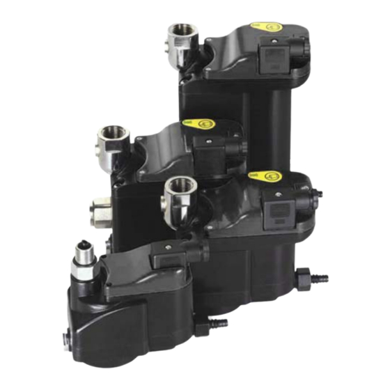
- Page 1 Installation, Operation and Maintenance Manual Electronic Condensate Drain 20-606 20-613 20-623 CELL:ASSY Parker Hannifin Corporation Industrial Gas Filtration and Generation Division 4087 Walden Avenue TI-20600 Lancaster, NY 14086 Tel: 716-686-6400 Fax: 877-857-3800...
-
Page 2: Manufacturer's Declaration
Parker Hannifin Corp., Filtration and Separation Division, 242 Neck Road Haverhill, MA 01835 herewith declares that the products electronic condensate drain models 20-606, 20-613, 20-623 are ETL listed conform to ANSI/UL STD 508 are certified to CAN/CSA STD C22.2 NO.14... -
Page 3: General Information
General Information About this operating manual Signs and symbols ► Procedures that must be completed in the indicated sequence are numbered. Items in lists are highlighted with grey boxes. Note: Always comply with these instructions to ensure safe and efficient operation of the machines and devices. - Page 4 Proper use of the condensate drain The condensate drain must only be used for the removal of standard condensates (condensed water and liquid oil) from compressed air systems. Any other use is deemed improper.
-
Page 5: Technical Description
Bottom condensate inlet* (not visible in diagram) Condensate outlet * not available in model 20-606 and 20-613 Function The condensate enters the unit through the inlet (1 or 2) and collects in the collecting chamber (3). When the collecting chamber is completely filled with condensate (4), the condensate is drained through the outlet (5) until the chamber is emptied. -
Page 6: Basic Requirements For Installation
The LED flashes slowly in red if the condensate cannot be drained off within the set time and an internal cleaning program has been started. After successful cleaning the drain returns to normal operating mode. If the cleaning program cannot be completed successfully, an emergency program is started and an alarm signal is issued (LED flashing rapidly in red). - Page 7 Observe downward slope into the condensate drain! Ensure that the condensate line entering the drain is properly sloped in a downward manner. Otherwise, an air bubble might prevent condensate from entering the drain. incorrect correct Install vent line! If the bottom condensate inlet is used, install a vent line.
- Page 8 Connection of condensate inlet 20-606 and 20-613 are equipped with a top condensate inlet only, while model 20-623 has a revolving top inlet and a bottom inlet for condensate. Note: For installation, we recommend using the appropriate Parker installation kit consisting of a ball valve with fittings.
- Page 9 Model 20-623 is equipped with a potential-free contact, in addition to the main power connection (not available for 20-606 and 20-613). Model 20-623 therefore features two connections with matching adapters: Adapter for supply voltage: magnetic valve connector "type B plug" industrial standard (0.43 in) 2 + PE (see figure, item 1)
- Page 10 Supply voltage Supply voltage Earth ground Type B plug supply voltage ► Push plug with seal int o the power adapter of the drain and screw it tight. ► Install a ground fault circuit interrupter, and plug the drain into the ground fault circuit interruptor.
- Page 11 The potential-free contact is a standard integrated feature of the condensate drain (not in model 20-606 and 20-613). To complete a function check at the contact, proceed as follows: ► Disconnect the unit from the power supply.
- Page 12 Monitoring of the Operation Danger of slipping! Water will condense on the drain’s outside when the condensate in the drain is colder than the environment. A puddle may form underneath the condensate drain if the condensed water drops to the ground. Use an appropriate collecting device to reduce the danger of slipping.
-
Page 13: Test Button
Test button The test button is used to open the valve manually; release the pressure from the condensate drain. The table below provides an overview of the test button functions: Interval and action Response Press and release test button Valve opens and closes Press and hold test button for max. -
Page 14: Maintenance
► Disconnect the power supply (remove the plug from the adapter). ► Dismantle condensate outlet by loosening nut (1) and pulling off the hose tail. ► Disconnect the drain: 20-606: — remove the condenate drain with complete filter base. The condensate inlet can be turned. -
Page 15: Annual Maintenance
Every 8,000 operating hours or once every 12 months (whichever occurs first), a number of parts in the condensate drain must be replaced as a precaution (normal preventive maintainance). For this purpose, Parker has assembled the ZLD-SK service kit containing these replacement parts (seals, springs,etc.). -
Page 16: Dimension Drawings
Dimension Drawings 20-606 20-613... - Page 17 20-623 Model 20-606 20-613 20-623 Dimensions (in) 4.33 3.97 4.80 4.21 4.37 4.84 0.47 0.47 0.47 — 2.87 3.66 — — 1.94 2.63 2.63 2.63 1.96 — — 5.74 5.47 6.45 5.03 4.76 — 4.17 4.21 4.88 1.73 2.63 —...
- Page 20 Parker Hannifin Corporation Industrial Gas Filtration and Generation Division 4087 Walden Avenue Lancaster, NY 14086 Tel: 716-686-6400 Fax: 877-857-3800 www.parker.com/igfg...
Need help?
Do you have a question about the 20-606 and is the answer not in the manual?
Questions and answers