Table of Contents
Advertisement
Quick Links
A MIDDLEBY COMPANY
OWNER'S
OPERATING
& INSTALLATION
MANUAL
PS629E-Series Electric Ovens
Model PS629E
© 2020 Middleby Marshall Inc.
is a registered trademark of Middleby Marshall, Inc. All rights reserved.
1
PS629E-Series Electric Ovens: English
Combinations:
• Single Oven
• Double Oven (Two-Stack)
• Triple Oven (Three-Stack)
P/N 77154 rev B
Advertisement
Table of Contents

Related Manuals for Middleby Marshall PS629E Series


Summary of Contents for Middleby Marshall PS629E Series
- Page 1 & INSTALLATION MANUAL Combinations: PS629E-Series Electric Ovens • Single Oven • Double Oven (Two-Stack) Model PS629E • Triple Oven (Three-Stack) © 2020 Middleby Marshall Inc. is a registered trademark of Middleby Marshall, Inc. All rights reserved. P/N 77154 rev B...
- Page 2 This manual must be kept in a prominent, easily reachable installing or servicing the equipment. location near the oven. Middleby Marshall suggests a service contract with a IMPORTANT Middleby Authorized Service Agent (ASA). An electrical wiring diagram for the oven is located inside DEFINITIONS the machinery compartment.
- Page 3 Buyer. This warranty is effective on Middleby Marshall equipment sold The foregoing shall be Seller’s sole and exclusive obligation and Buyer’s sole and exclusive remedy for any action, whether in breach on, or after January 1st, 2007.
-
Page 4: Table Of Contents
SECTION 1 DESCRIPTION ..........5 V. TEMPERATURE CONTROLLER OPERATION ..28 MODEL IDENTIFICATION ........5 A. Operation Adjustments ....... 28 II. PS629E SERIES SPECIFICATIONS ....... 6 B. Programming Adjustments ......28 III. COMPONENT FUNCTION ........7 SECTION 4 MAINTENANCE ..........31 A. -
Page 5: Section 1 Description
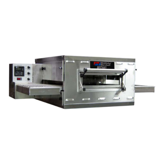
DESCRIPTION SECTION 1 DESCRIPTION I. MODEL IDENTIFICATION The Middleby Marshall PS629E-Series has a 15" (381mm) wide front window and reversible conveyor. The PS629 may be used either as a single oven or stacked for use as double or triple ovens. -
Page 6: Ps629E Series Specifications
SECTION 1 DESCRIPTION II. PS629E SERIES SPECIFICATIONS RECOMMENDED MINIMUM CLEARANCES There are no recommended clearances from the rear, control end, or non-control end of the oven to the wall. PS629E SERIES OVEN SPECIFICATIONS Overall Length Height Maximum Bake Heating Baking... -
Page 7: Component Function
SECTION 1 DESCRIPTION PS629E-Series Oven Components Locations III. COMPONENT FUNCTION A. Conveyor Motor and Conveyor Belt The conveyor belt is driven by a variable-speed electric motor (Figure 5) operating through a gear reducer. The motor speed is controlled by a digital control. -
Page 8: Blower Fan
SECTION 1 DESCRIPTION B. Blower Fan The blower fans are located at the rear of the oven. These blowers force heated air through the air fingers. The BLOWER switch must be set to “ON” or “I” for oven warmup and baking. C. -
Page 9: Air Fingers And Blank Plates
E. Air Fingers and Blank Plates E2. Blank Plates See Figure 8. 1. Blank Plates - The Blank Plates are available to install on the plenum where an air finger is not E1. Air Fingers required. An Air Finger Assembly is made up of three parts: 1. - Page 10 SECTION 1 DESCRIPTION NOTES...
-
Page 11: Section 2 Installation
SECTION 2 INSTALLATION SECTION 2 INSTALLATION NOTE: All aspects of the oven installation, including WARNING placement, utility connections, ventilation Keep the appliance area free and clear of requirements, must conform with any applicable local, combustibles. national, or international codes. These codes supersede the requirements and guidelines provided WARNING in this manual. -
Page 12: Unloading, Dimensions, And Rough-In
I. UNLOADING, DIMENSIONS, AND CAUTION It is recommended that the oven be placed ROUGH-IN under a ventilation hood for adequate air supply Your Middleby Marshall PS629E-Series Oven is and ventilation. shipped partially assembled. It will arrive in a carton on a crate. CAUTION... - Page 13 SECTION 3 OPERATION PARTS LIST FOR SERIES PS629E ELECTRIC OVEN INSTALLATION KIT Single and Double Stack Ovens ITEM NO. PART NO. DESCRIPTION 3101908 LEG 4″ AD FT 62208 INSULATION BOTTOM TRAY 62206 BOTTOM TRAY WELDMENT 61650 TOP COVER 51387 SCREW MSSLT THREAD 8-32 × 1/2, 18-8 77154 OWNER’S OPERATING &...
- Page 14 SECTION 3 OPERATION PARTS LIST FOR SERIES PS629E ELECTRIC OVEN INSTALLATION KIT Triple Stack Oven ITEM NO. PART NO. DESCRIPTION 3101908 LEG 4″ AD FT 62208 INSULATION BOTTOM TRAY 62206 BOTTOM TRAY WELDMENT 61650 TOP COVER 51387 SCREW MSSLT THREAD 8-32 × 1/2, 18-8 77154 OWNER’S OPERATING &...
- Page 15 SECTION 3 OPERATION The Opening Height is Adjustable from 2-1/4" (57mm) minimum to 3-3/4" (95mm) maximum in 1/2" (13mm) increments. Model PS629E Single Oven Dimensions...
- Page 16 SECTION 3 OPERATION The Opening Height is Adjustable from 2-1/4" (57mm) minimum to 3-3/4" (95mm) maximum in 1/2" (13mm) increments. P/N 59227 is shown in its correct installed position. Model PS629E Double Oven Dimensions...
- Page 17 SECTION 3 OPERATION The Opening Height is Adjustable from from 2-1/4" (57mm) minimum to 3-3/4" (95mm) maximum in 1/2" (13mm) increments. P/N 59227 is shown in its correct installed position. Model PS629E Triple Oven Dimensions...
- Page 18 SECTION 3 OPERATION Model PS629E Dimensions with Optional Legs/Casters...
-
Page 19: Ventilation Guidelines
If space permits, service should be located near the recommended for the PS629E Series Middleby control console end of the oven(s) to allow convenient Marshall conveyorized electric ovens. access to safety switches. Local codes and conditions vary greatly from one area to another and must be complied with. -
Page 20: Electrical Connection Information For Ps629E-Series Ovens
SECTION 3 OPERATION owner’s responsibility. Improper ventilation can inhibit A fused disconnect switch or a main circuit breaker (customer furnished) MUST be installed in the electric oven performance. supply line for each oven; it is recommended that this Please Note: There is now one heat guard on switch/circuit breaker have lockout/tagout capability. -
Page 21: Electric Supply For Electrically Heated Ovens
SECTION 3 OPERATION IV. ELECTRIC SUPPLY FOR ELECTRICALLY HEATED OVENS Power requirements for electrically heated ovens are usually 208 - 240VAC, 1-phase, 3-wire (2 “hot”, 1 ground) or 208-240VAC, 3-phase, 4-wire (3 “hot”, 1 ground), although ovens built for export can have power requirements of 380VAC. - Page 22 SECTION 3 OPERATION NOTES...
-
Page 23: Section 3 Operation
SECTION 3 OPERATION SECTION 3 OPERATION I. CONTROL FUNCTIONS PS629E-Series Oven Control Functions B. Blower Switch WARNING The blower switch must be “ON” or “I” for the main Possibility of injury from rotating parts and blowers to come on and to permit the oven to run. The electric shock. -
Page 24: Temperature Controller
SECTION 3 OPERATION D. Temperature Controller The temperature controller contains a low-limit switch which allows the oven to cool down to 200°F (93°C) The temperature controller is a solid-state, PID type to before shutting off the blower. An OVER TEMP LED maintain the temperature set point. -
Page 25: Measuring Conveyor Speed
SECTION 3 OPERATION III. MEASURING CONVEYOR SPEED See Figure 22 and Figure 23. To check conveyor speed, place a product item at the entrance end of baking chamber as shown. Time how long it takes for the leading edge of the item to go from the entrance end of the baking chamber to the exit end. -
Page 26: Step-By-Step Operation
SECTION 3 OPERATION Control Panel Daily Maintenance Section for the fan intake IV. STEP-BY-STEP OPERATION checking procedure. A. Daily Start-up Procedure IMPORTANT 1. Check that the circuit breaker/fused disconnect is The cooling fan operates when the BLOWER switch in the on (closed) position. is turned “ON”... -
Page 27: Daily Shutdown Procedure
SECTION 3 OPERATION 5. Set the conveyor speed for 1 8. With the HEAT ON LED lit, press the Scroll key to 10 minutes using the up one time from the “Set Point Only” display. The and down arrow buttons. The actual temperature will appear in the lower conveyor speed... -
Page 28: Temperature Controller Operation
SECTION 3 OPERATION V. TEMPERATURE CONTROLLER OPERATION NOTE: After 1 minute of no key activity, the controller will go to “Set Point Only” with the lower display blank. Operation Adjustments B. Programming Adjustments Adjusting the Set Point Adjusting Power Output The set point appears in the upper Press the Star and Up keys together for 3 seconds. - Page 29 Follow the procedures under Daily Shutdown Procedures in this section lit, food product is exceeded 650°F (343°C), and to shut down the oven. Contact your Middleby Marshall Authorized undercooked the heating system was Service Agent to determine and correct the cause of the condition to automatically shut down.
- Page 30 SECTION 3 OPERATION NOTES...
-
Page 31: Section 4 Maintenance
NOTICE ANY replacement parts that require access to the interior of the oven may ONLY be replaced by a Middleby Marshall Authorized Service Agent. It is also strongly recommended that the 3-Month Maintenance and 6-Month Maintenance procedures in this section... -
Page 32: Conveyor Belt (Figure 26)
For heavier cleaning of baked-on grease and carbon deposits, use a non-caustic cleaner that will not react with the aluminized finger manifold surfaces. You can order non-caustic cleaner from your local authorized Middleby Marshall Parts Distributor. Conveyor Belt and Crumb Pan Cleaning... -
Page 33: Removing Conveyor From Oven And Cleaning
SECTION 4 MAINTENANCE A. Removing Conveyor from Oven and Cleaning 1. Remove entry and exit trays. 2. Loosen two wing screws on the upper end plugs and remove the end plugs. 3. Remove motor housing guard (Figure 28). 4. Lift conveyor and remove chain (Figure 29). 5. -
Page 34: Air Fingers Disassembly And Cleaning
SECTION 4 MAINTENANCE 8. Clean the stainless steel conveyor by either soaking in a hot, strong detergent solution or using a caustic cleaner. B. Air Fingers Disassembly and Cleaning 1. Get a felt tip pen. As the air fingers are removed, you need it to mark all parts of the fingers. - Page 35 SECTION 4 MAINTENANCE 6. The outer finger plate is stainless and may be cleaned by either soaking in a hot, strong detergent solution or using a caustic cleaner. 3. With air fingers out, place them in an upright position to remove the outer plate. 4.
-
Page 36: Reassembly Of Air Fingers
SECTION 4 MAINTENANCE C. Reassembly of Air Fingers 4. Reinstall the air fingers by pushing in at the back side. Remember to replace them according to the 1. Gather the air finger parts for reassembly. Air numbers marked on them when they were fingers are made up of one inner plate, one outer removed. - Page 37 SECTION 4 MAINTENANCE...
- Page 38 SECTION 4 MAINTENANCE 5. Install fingers and blank plates correctly with edges interlocked and no space between edges. Correct - Edges Overlap Completely...
-
Page 39: Conveyor Reassembly Into Oven
SECTION 4 MAINTENANCE D. Conveyor Reassembly Into Oven 3. If conveyor belt is still not under proper tension, an entire link must be removed. Use the following 1. Reinstall lower end plug. Be sure to tighten the procedure “F. Conveyor Belt Link Removal” to wing screw on the end plug. - Page 40 SECTION 4 MAINTENANCE 2. Using long nose pliers, unhook master links at left end of conveyor as shown in Figure 47. 3. Remove the outside master links on the right and left sides of the conveyor belt as shown in Figure NOTE: Before connecting the inside master links, notice that these links have a correct position (Figure 50).
-
Page 41: Attaching Drive Chain
SECTION 4 MAINTENANCE 3. The angle plate located on the underside of the conveyor must be against the lower end plug. This is true on both sides of oven. 7. Reconnect the outside master links. 8. Replace all parts removed from the oven. 4. -
Page 42: Maintenance - Every 3 Months
SECTION 4 MAINTENANCE III. MAINTENANCE - EVERY 3 MONTHS IV. MAINTENANCE - EVERY 6 MONTHS A. Oven Vent Check WARNING Shut OFF all electrical power and lock/tag out Check your oven venting system. the switch before attempting maintenance work. NOTICE •... -
Page 43: Key Spare Parts Kit
(Figure 59). (The kit can be purchased when the oven • P/N 77156 – 380V (12 kW, 3 Phase+Neutral) is ordered, or later, from a Middleby Marshall • Authorized Parts Distributor). The kit contains many of P/N 77157 – 208V (10 kW, Single Phase) the crucial parts that can reduce serious downtime and •... - Page 44 SECTION 4 MAINTENANCE...
-
Page 45: Section 5 Troubleshooting
OVEN DOES NOT HEAT Incorrect switch position. Check to see if both BLOWER switch and HEAT switch are in the “ON” or “I” position. If oven does not heat, call your Middleby Marshall Service Agency. BLOWER MOTOR IS Air fingers reassembled Assemble air fingers correctly after cleaning. - Page 46 SECTION 5 TROUBLESHOOTING SYMPTOM PROBLEM SOLUTION OVEN WILL NOT Electrical power may not Check that the circuit breaker/fused disconnect is TURN ON AT ALL be reaching the oven, or turned on. the controls may be set Check that the BLOWER switch is in the “ON” (“I”) incorrectly.
-
Page 47: Section 6 Electrical Schematics
SECTION 6 ELECTRICAL SCHEMATICS SECTION 6 ELECTRICAL SCHEMATICS Wiring Diagram, E208-240V 3PH PS629E • 74629 REV F... - Page 48 SECTION 5 TROUBLESHOOTING Wiring Diagram, E230V 1PH CE PS629E • 74665 REV F...
- Page 49 SECTION 6 ELECTRICAL SCHEMATICS Wiring Diagram, E380V 3PH PS629E • 74667 REV F...
- Page 50 SECTION 5 TROUBLESHOOTING Wiring Diagram, E380V 3PH CE PS629E • 74669 REV F...
- Page 51 SECTION 6 ELECTRICAL SCHEMATICS...
- Page 52 NOTICE During the warranty period, ALL parts replacement and servicing should be performed by your Middleby Marshall Authorized Service Agent. Service that is performed by parties other than your Middleby Marshall Authorized Service Agent may void your warranty.
Need help?
Do you have a question about the PS629E Series and is the answer not in the manual?
Questions and answers