Table of Contents
Advertisement
A MIDDLEBY COMPANY
OWNER'S
OPERATING
& INSTALLATION
MANUAL
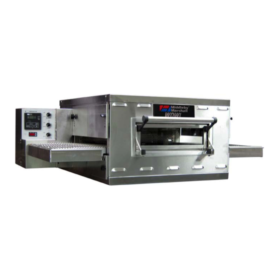
PS629G-Series Gas Ovens
Model PS629G
© 2020 Middleby Marshall Inc.
is a registered trademark of Middleby Marshall, Inc. All rights reserved.
1
PS629G-Series Gas Ovens: English
Combinations:
• Single Oven
• Double Oven (Two-Stack)
• Triple Oven (Three-Stack)
P/N 77109 rev B
Advertisement
Table of Contents

Related Manuals for Middleby Marshall PS629G Series


Summary of Contents for Middleby Marshall PS629G Series
- Page 1 & INSTALLATION MANUAL Combinations: PS629G-Series Gas Ovens • Single Oven Model PS629G • Double Oven (Two-Stack) • Triple Oven (Three-Stack) © 2020 Middleby Marshall Inc. is a registered trademark of Middleby Marshall, Inc. All rights reserved. P/N 77109 rev B...
- Page 2 For domestic and standard export ovens, instructions are installing or servicing the equipment. included in the Gas Conversion Kit. Middleby Marshall suggests a service contract with a IMPORTANT Middleby Authorized Service Agent (ASA). An electrical wiring diagram for the oven is located inside DEFINITIONS the machinery compartment.
- Page 3 Seller shall not be liable for any prospective or lost profits of the buyer. or lost profits of Buyer. This warranty is effective on Middleby Marshall equipment sold The foregoing shall be Seller’s sole and exclusive obligation and on, or after January 1st, 2007.
-
Page 4: Table Of Contents
SECTION 1 DESCRIPTION ..........5 III. MEASURING CONVEYOR SPEED ....... 27 MODEL IDENTIFICATION ........5 IV. STEP-BY-STEP OPERATION ....... 28 II. PS629G SERIES SPECIFICATIONS ...... 6 A. Daily Start-up Procedure ........28 III. COMPONENT FUNCTION ........7 B. Daily Shutdown Procedure ......29 A. -
Page 5: Section 1 Description
DESCRIPTION SECTION 1 DESCRIPTION I. MODEL IDENTIFICATION The Middleby Marshall PS629G-Series has a 15" (381mm) wide front window and reversible conveyor. The PS629 may be used either as a single oven or stacked for use as double or triple ovens. -
Page 6: Ps629G Series Specifications
SECTION 1 DESCRIPTION II. PS629G SERIES SPECIFICATIONS RECOMMENDED MINIMUM CLEARANCES There are no recommended clearances from the rear, control end, or non-control end of the oven to the wall. PS629G SERIES OVEN SPECIFICATIONS Overall Length Height Maximum Bake Heating Baking... -
Page 7: Component Function
SECTION 1 DESCRIPTION PS629G-Series Oven Components Locations III. COMPONENT FUNCTION A. Conveyor Motor and Conveyor Belt The conveyor belt is driven by a variable-speed electric motor (Figure 5) operating through a gear reducer. The motor speed is controlled by a digital control. -
Page 8: Blower Fan
SECTION 1 DESCRIPTION B. Blower Fan The blower fans are located at the rear of the oven. These blowers force heated air through the air fingers. The BLOWER switch must be set to “ON” or “I” for oven warmup and baking. C. -
Page 9: Air Fingers And Blank Plates
E. Air Fingers and Blank Plates E2. Blank Plates See Figure 8. 1. Blank Plates - The Blank Plates are available to install on the plenum where an air finger is not E1. Air Fingers required. An Air Finger Assembly is made up of three parts: 1. - Page 10 SECTION 1 DESCRIPTION Blank Plates (two sizes) and an Air Finger...
-
Page 11: Section 2 Installation
SECTION 2 INSTALLATION SECTION 2 INSTALLATION WARNING NOTICE There must be adequate clearance between the After conversions, readjustments, oven and combustible construction. Clearance must service work on the oven: also be provided for servicing and for proper • Perform a gas leak test. operation. -
Page 12: Unloading, Dimensions, And Rough-In
I. UNLOADING, DIMENSIONS, AND CAUTION ROUGH-IN It is recommended that the oven be placed under a ventilation hood for adequate air supply Your Middleby Marshall PS629G-Series Oven is and ventilation. shipped partially assembled. It will arrive in a carton on a crate. CAUTION... - Page 13 SECTION 2 INSTALLATION PARTS LIST FOR SERIES PS629G GAS OVEN INSTALLATION KIT Double Stack Oven ITEM NO. PART NO. DESCRIPTION 62208 INSULATION BOTTOM TRAY 62206 BOTTOM TRAY WELDMENT 61650 TOP COVER 51387 SCREW MSSLT THREAD 8-32 × 1/2, 18-8 3101908 LEG 4"...
- Page 14 SECTION 2 INSTALLATION The Opening Height is Adjustable from 2-1/4" (57mm) minimum to 3-3/4" (95mm) maximum in 1/2" (13mm) increments. Model PS629G Single Oven Dimensions...
- Page 15 SECTION 2 INSTALLATION The Opening Height is Adjustable from 2-1/4" (57mm) minimum to 3-3/4" (95mm) maximum in 1/2" (13mm) increments. P/N 59227 is shown in its correct installed position. Model PS629G Double Oven Dimensions...
- Page 16 SECTION 2 INSTALLATION The Opening Height is Adjustable from from 2-1/4" (57mm) minimum to 3-3/4" (95mm) maximum in 1/2" (13mm) increments. P/N 59227 is shown in its correct installed position. Model PS629G Triple Oven Dimensions...
- Page 17 SECTION 2 INSTALLATION Model PS629G Dimensions with Optional Legs/Casters...
-
Page 18: Ventilation Guidelines
SECTION 2 INSTALLATION UTILITY ROUGH-IN DIMENSIONS AND POSITIONING FOR PS629G-SERIES OVENS WARNING Do not use conduit or gas line for ground connection. CAUTION It is recommended that the oven be placed under a ventilation hood for adequate air supply and ventilation. 24"... -
Page 19: Electrical Connection Information For Ps629G-Series Ovens
SECTION 2 INSTALLATION Please Note: There are now two “stand off” plate air vents that must be installed in the field. C-channel brackets are installed in the vertical plane using existing screws to support plate air vents, using the upper and lower Key Hole openings in the C-channels. -
Page 20: Electric Supply For Gas Heated Ovens
SECTION 2 INSTALLATION IV. ELECTRIC SUPPLY FOR GAS NOTICE HEATED OVENS To prevent damage to the control valve regulator during initial turn-on of gas, it is very important to open Power requirements for gas heated ovens are 208 - the manual shutoff valve very slowly. 240VAC, 1-phase, 3-wire (2 “hot”, 1 ground). -
Page 21: Adjusting The Maximum Pressure Setting
SECTION 2 INSTALLATION 4. Energize operator, set control in operation and wait until an outlet pressure is recorded on pressure gauge. 5. If minimum rate pressure needs adjustment, use a 5mm wrench to turn adjustment screw for minimum pressure setting (clockwise to increase or counter-clockwise to decrease pressure), while securely holding the 8mm wrench in place on the maximum pressure adjustmet nut, until the... -
Page 22: Checkout
Figure 20; start-ups, conversions, and service work to be however, compliance with the applicable standards performed by a Middleby Marshall Authorized and regulations is mandatory. Service Agent. The installation, start-up and changes required when changing from one gas... - Page 23 SECTION 2 INSTALLATION Open the main gas supply valve. Switch the circuit breaker/fused disconnect to the ON (“I”) position. Start the oven according the directions in the Operation section of this Manual. Adjust the temperature controller to the maximum setting 600°F (316°C). Measure the supply (inlet) pressure.
- Page 24 SECTION 2 INSTALLATION NOTES...
-
Page 25: Section 3 Operation
SECTION 3 OPERATION SECTION 3 OPERATION I. CONTROL FUNCTIONS PS629G-Series Oven Control Functions B. Blower Switch WARNING The blower switch must be “ON” or “I” for the main Possibility of injury from rotating parts and blowers to come on and to permit the oven to run. The electric shock. -
Page 26: Conveyor Switch And Speed Controller
SECTION 3 OPERATION Interior View of Control Console E. Conveyor Switch and Speed Controller On the control panel is an on-off switch for the conveyor motor, and under the temperature controller is the conveyor speed controller. The digital controller can be adjusted from 1-10 min. bake time (conveyor speed). -
Page 27: Measuring Conveyor Speed
SECTION 3 OPERATION III. MEASURING CONVEYOR SPEED See Figure 26 and Figure 27. To check conveyor speed, place a product item at the entrance end of baking chamber as shown. Time how long it takes for the leading edge of the item to go from the entrance end of the baking chamber to the exit end. -
Page 28: Step-By-Step Operation
SECTION 3 OPERATION Control Panel IV. STEP-BY-STEP OPERATION Daily Maintenance Section for the fan intake checking procedure. A. Daily Start-up Procedure IMPORTANT 1. Check that the circuit breaker/fused disconnect is The cooling fan operates when the BLOWER switch in the on (closed) position. is turned “ON”... -
Page 29: Daily Shutdown Procedure
SECTION 3 OPERATION 5. Set the conveyor speed for 1 8. With the HEAT ON LED lit, press the Scroll key to 10 minutes using the up one time from the “Set Point Only” display. The and down arrow buttons. The actual temperature will appear in the lower conveyor speed... -
Page 30: Temperature Controller Operation
SECTION 3 OPERATION V. TEMPERATURE CONTROLLER OPERATION NOTE: After 1 minute of no key activity, the controller will go to “Set Point Only” with the lower display blank. A. Operation Adjustments B. Programming Adjustments Adjusting the Set Point Adjusting Power Output The set point appears in the upper Press the Star and Up keys together for 3 seconds. - Page 31 Follow the procedures under Daily Shutdown Procedures in this section exceeded 650°F (343°C), and lit, food product is to shut down the oven. Contact your Middleby Marshall Authorized the burner was automatically undercooked Service Agent to determine and correct the cause of the condition to shut down.
- Page 32 SECTION 3 OPERATION NOTES...
-
Page 33: Section 4 Maintenance
ONLY be replaced by a perform the following procedure: Middleby Marshall Authorized Service Agent. It is also 1. Switch off the oven and allow it to cool. Do NOT strongly recommended that the 3-Month Maintenance service the oven while it is warm. -
Page 34: Crumb Pans (Figure 29)
Use a damp cloth for light cleaning. For heavier cleaning of baked-on grease and carbon deposits, use a non-caustic cleaner that will not react with the aluminized finger manifold surfaces. You can order non-caustic cleaner from your local authorized Middleby Marshall Parts Distributor. -
Page 35: Removing Conveyor From Oven And Cleaning
SECTION 4 MAINTENANCE A. Removing Conveyor from Oven and Cleaning 1. Remove entry and exit trays. 2. Loosen two wing screws on the upper end plugs and remove the end plugs. 3. Remove motor housing guard (Figure 32). 4. Lift conveyor and remove chain (Figure 33). 5. -
Page 36: Air Fingers Disassembly And Cleaning
SECTION 4 MAINTENANCE 8. Clean the stainless steel conveyor by either soaking in a hot, strong detergent solution or using a caustic cleaner. B. Air Fingers Disassembly and Cleaning 1. Get a felt tip pen. As the air fingers are removed, you need it to mark all parts of the fingers. - Page 37 SECTION 4 MAINTENANCE 6. The outer finger plate is stainless and may be cleaned by either soaking in a hot, strong detergent solution or using a caustic cleaner. 3. With air fingers out, place them in an upright position to remove the outer plate. 4.
-
Page 38: Reassembly Of Air Fingers
SECTION 4 MAINTENANCE C. Reassembly of Air Fingers 4. Reinstall the air fingers by pushing in at the back side. Remember to replace them according to the 1. Gather the air finger parts for reassembly. Air numbers marked on them when they were fingers are made up of one inner plate, one outer removed. - Page 39 SECTION 4 MAINTENANCE...
- Page 40 SECTION 4 MAINTENANCE 5. Install fingers and blank plates correctly with edges interlocked and no space between edges. Correct - Edges Overlap Completely...
-
Page 41: Conveyor Reassembly Into Oven
SECTION 4 MAINTENANCE D. Conveyor Reassembly Into Oven 3. If conveyor belt is still not under proper tension, an entire link must be removed. Use the following 1. Reinstall lower end plug. Be sure to tighten the procedure “F. Conveyor Belt Link Removal” to wing screw on the end plug. - Page 42 SECTION 4 MAINTENANCE 2. Using long nose pliers, unhook master links at left end of conveyor as shown in Figure 51. 3. Remove the outside master links on the right and left sides of the conveyor belt as shown in Figure 52.
-
Page 43: Attaching Drive Chain
SECTION 4 MAINTENANCE 3. The angle plate located on the underside of the conveyor must be against the lower end plug. This is true on both sides of oven. 7. Reconnect the outside master links. 8. Replace all parts removed from the oven. 4. -
Page 44: Maintenance - Every 3 Months
SECTION 4 MAINTENANCE III. MAINTENANCE - EVERY 3 MONTHS IV. MAINTENANCE - EVERY 6 MONTHS A. Oven Vent Check WARNING Shut OFF all electrical power and lock/tag out Check your oven venting system. the switch before attempting maintenance work. B. Burner Inspection Inspect and clean the burner nozzle and the spark NOTE: It is recommended that the 3-month electrode assembly. -
Page 45: Key Spare Parts Kit P/N 77110
(Figure 63). (The kit can be purchased when the oven your Middleby Marshall Authorized Parts Distributor. is ordered, or later, from a Middleby Marshall Authorized Parts Distributor). The kit contains many of PS629G-SERIES GAS OVEN KEY SPARE PARTS KIT (Figure 63) ITEM PART NO. - Page 46 SECTION 4 MAINTENANCE NOTES...
-
Page 47: Section 5 Troubleshooting
OVEN DOES NOT HEAT Incorrect switch position. Check to see if both BLOWER switch and HEAT switch are in the “ON” or “I” position. If oven does not heat, call your Middleby Marshall Service Agency BLOWER MOTOR IS Air fingers reassembled Assemble air fingers correctly after cleaning. - Page 48 SECTION 5 TROUBLESHOOTING SYMPTOM PROBLEM SOLUTION OVEN WILL NOT Electrical power may not Check that the circuit breaker/fused disconnect is TURN ON AT ALL be reaching the oven, or turned on. the controls may be set Check that the BLOWER switch is in the “ON” (“I”) incorrectly.
- Page 49 SECTION 5 TROUBLESHOOTING NOTES...
-
Page 51: Section 6 Electrical Schematics
SECTION 6 ELECTRICAL SCHEMATICS SECTION 6 ELECTRICAL SCHEMATICS Wiring Diagram, G208-240 50/60 W/INV PS629G • 74623 REV F... - Page 52 NOTICE During the warranty period, ALL parts replacement and servicing should be performed by your Middleby Marshall Authorized Service Agent. Service that is performed by parties other than your Middleby Marshall Authorized Service Agent may void your warranty.
Need help?
Do you have a question about the PS629G Series and is the answer not in the manual?
Questions and answers