Middleby Marshall PS570 Series Owner's Operating & Installation Manual
Hide thumbs
Also See for PS570 Series:
- Technical & service manual (182 pages) ,
- Technical & service manual (182 pages)

Related Manuals for Middleby Marshall PS570 Series


Summary of Contents for Middleby Marshall PS570 Series
- Page 1 A MIDDLEBY COMPANY UNE SOCIÉTÉ MIDDLEBY owner's manuel operating d'utilisation & installation et d'installation manual LE FOUR À GAZ MODEL PS570 MODÉLE PS570 GAS OVEN Piéce No. Prix $30,00...
- Page 2 CONTACT YOUR LOCAL SERVICE COMPANY TO PERFORM MAINTENANCE AND REPAIRS. A SERVICE AGENT DIRECTORY IS SUPPLIED IN YOUR INSTALLATION KIT. NOTICE Using any parts other than genuine Middleby Marshall factory manufactured parts relieves the manufacturer of all warranty and liability. NOTICE Middleby Marshall (Manufacturer) reserves the right to change specifications at any time.
- Page 3 NOTE : AVERTISSEMENT AFFICHEZ DANS UN ENDROIT BIEN EN VUE LE NUMÉRO DE TÉLÉPHONE D’URGENCE DE VOTRE COMPAGNIE DU GAZ ET LES DIRECTIVES À SUIVRE EN CAS DE DÉGAGEMENT D’UNE ODEUR DE GAZ. Les directives à suivre en cas de dégagement d’une odeur de gaz peuvent être obtenues en s’adressant à...
- Page 4 à gagner de l’acheteur. Middleby Marshall Inc. • 1400 Toastmaster Drive • Elgin, IL 60120 • USA • (847) 741-3300 • FAX (847) 741-4406 Middleby Corporation Service Hotline 1-800-238-8444 Ligne directe d’aide technique de la Middleby Corporation 1-800-238-8444...
- Page 5 MIDDLEBY MARSHALL INC. GARANTIE LIMITÉE DES FOURS MIDDLEBY MARSHALL INC. OVEN LIMITED WARRANTY (Hors des États-Unis) (Non U.S.A.) Le vendeur garantit l’équipement qu’il a fabriqué contre tout défaut de matières et de fabrication dont il est responsable. Son obligation aux termes de la présente garantie se limite, à...
-
Page 6: Table Of Contents
TABLE OF CONTENTS TABLE DE MATIÉRES SECTION 1 - DESCRIPTION page page OVEN SPECIFICATION CHARTS ......1-2 SECTION 2 - INSTALLATION INSTALLATION KIT ..........2-4 GAS OVEN ROUGH-IN ......... 2-6 SECTION 3 - OPERATION MEASURING THE CONVEYOR SPEED ....3-3 SUGGESTED BAKE TIMES AND TEMPERATURES .......... - Page 7 SECTION 4 - MAINTENANCE KEY SPARE PARTS KIT ........4-24 SECTION 5 - TROUBLESHOOTING OWNERS TROUBLESHOOTING CHARTS ... 5-1 SECTION 6 - ELECTRICAL SCHEMATICS...
- Page 8 NOTES:...
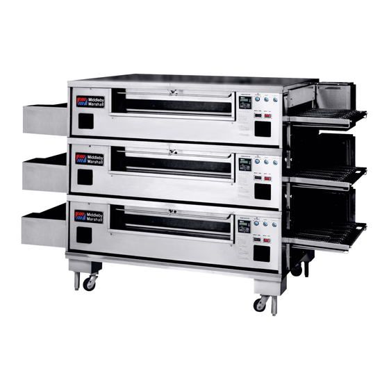
- Page 9 SECTION 1 SECTION 1 DESCRIPTION DESCRIPTION SECTION 1 SECTION 1 DESCRIPTION DESCRIPTION I. MODEL IDENTIFICATION I. IDENTIFICATION DU MODÈLE Figure 1-1. Single Oven Figure 1-2. Double Oven Figure 1-4. Quad Oven Figure 1-3. Triple Oven...
- Page 10 SECTION 1 SECTION 1 DESCRIPTION DESCRIPTION OVEN SPECIFICATIONS CHART OF ORIFICE SIZES AND GAS PRESSURES Main Orifice I.D. Pilot Orifice I.D. Bypass Orifice I.D. Supply (Inlet) Orifice (Manifold) Type (Full Flame) (Inlet) Pressure Pressure Natural 0.250" (6.35mm) 0.028" (0.71mm) 0.065" (1.65mm/#53 drill) 6-12"...
- Page 11 SECTION 1 SECTION 1 DESCRIPTION DESCRIPTION CARACTÉRISTIQUES DES FOURS CARACTÉRISTIQUES DE l’ALIMENTATION EN GAZ Type Buse de Principal dia. int. Buse de Veilleuse Buse de flamme mini Pression d'alimentation Pression de buse de gaz (flamme haute) dia. int. dia. int. (arrivée) (distributeur) Naturel...
- Page 12 SECTION 1 SECTION 1 DESCRIPTION DESCRIPTION II. PRINCIPLE OF AIR FLOW II. PRINCIPE DE LA CIRCULATION D’AIR Figure 1-5 - AIR DELIVERY SYSTEM...
- Page 13 SECTION 1 SECTION 1 DESCRIPTION DESCRIPTION Figure 1-6. Air Fingers Showing Air Passing Through Inner Plate And Outer Plate Which Forms High Velocity Columns Of Air To Product A. Heat Transfer and How It Works Conduction : Conduction: Radiation : Radiation: Convection: Convection :...
- Page 14 SECTION 1 SECTION 1 DESCRIPTION DESCRIPTION II. PRINCIPLE OF AIR FLOW (continued) II. PRINCIPE DE LA CIRCULATION D’AIR (suite) B. Air Fingers NOTE: Figure 1-7. Component Location...
- Page 15 SECTION 1 SECTION 1 DESCRIPTION DESCRIPTION III. COMPONENT FUNCTION III. FONCTIONS DES COMPOSANTS A. Conveyor B. Gas Burner C. Front Window D. Cooling Fans E. Blower Figure 1-8. Cooling Fan...
- Page 16 SECTION 1 SECTION 1 DESCRIPTION DESCRIPTION F. Air Fingers 1. Outer Plate- radiant finger 2. Inner Plate 3. Finger Manifold-...
- Page 17 SECTION 1 SECTION 1 DESCRIPTION DESCRIPTION Figure 1-9. Fingers...
- Page 18 SECTION 1 SECTION 1 DESCRIPTION DESCRIPTION NOTES: 1-10...
-
Page 19: Section 2 - Installation
SECTION 2 SECTION 2 INSTALLATION INSTALLATION SECTION 2 SECTION 2 INSTALLATION INSTALLATION I. UNLOADING/UNPACKING I. DÉCHARGEMENT/DÉBALLAGE NOTE NOTE Il faut respecter un dégagement adéquat There must be adequate clearance entre le four et les parois combustibles des between the oven and combustible bâtiments. - Page 20 SECTION 2 SECTION 2 INSTALLATION INSTALLATION II. VENTILATION SYSTEM II. SYSTÈME D’AÉRATION IMPORTANT IMPORTANT Where local or national codes require the installation of fire suppression equipment or other supplementary equipment, DO NOT mount the equipment directly to the oven. MOUNTING SUCH EQUIPMENT ON THE OVEN MAY: LE MONTAGE DE L’ÉQUIPEMENT SUR LE FOUR PEUT: •...
- Page 21 SECTION 2 SECTION 2 INSTALLATION INSTALLATION Figure 2-1 - Ventilation Hood Dimensions (RECOMMENDATIONS ONLY)
-
Page 22: Installation Kit
SECTION 2 SECTION 2 INSTALLATION INSTALLATION INSTALLATION KIT JEU D’INSTALLATION NOTE: One Installation Kit is required for each oven cavity. Order ONE kit for a single oven, TWO kits for a double oven, etc. NOTE: Qty. Qte. Item No. Single Belt Split Belt Part No. - Page 23 SECTION 2 SECTION 2 INSTALLATION INSTALLATION Figure 2-2 - Installation Kit Figure 2-3 - Base Pad Kit...
-
Page 24: Gas Oven Rough-In
SECTION 2 SECTION 2 INSTALLATION INSTALLATION GAS OVEN ROUGH-IN RACCORDEMENTS DES FOURS À GAZ UTILITY ROUGH-IN DIMENSIONS AND DIMENSIONS ET POSITION DES POSITIONING RACCORDEMENTS POUR LES FOURS Rear View Four Simple : 641mm (25,25 po.) Four Double : 540mm (21,25 po.) Four Triple : 143mm (5,625 po.) Four Quadruple : 79mm (3,125 po.) - Page 25 SECTION 2 SECTION 2 INSTALLATION INSTALLATION MINIMUM GAS METER RATING MINIMUM GAS PIPE SIZE Natural: Must be a dedicated line. For runs over 200 ft. (200m), consult the factory. Propane: Must be a dedicated line. For runs over 200 ft. (200m), consult the factory. GAS VALVES full flow REQUIRED SUPPLY GAS PRESSURE...
- Page 26 SECTION 2 SECTION 2 INSTALLATION INSTALLATION III. ELECTRICAL CONNECTION III. ALIMENTATION EN ÉLECTRICITÉ WARNING AVERTISSEMENT NOTE: The electric supply installation must satisfy the NOTE : requirements of the appropriate statutory authority, such as the National Electrical Code (NEC), ANSI/NFPA70, (U.S.A.); the Canadian Electrical Code, CSA C22.2;...
- Page 27 SECTION 2 SECTION 2 INSTALLATION INSTALLATION CAUTION ATTENTION CAUTION ATTENTION DO NOT CONNECT BLACK NE PAS RACCORDER LE WIRE TO HIGH LEG. CONDUCTEUR NOIR À UNE VOLTAGE OF THE BLACK AND BRANCHE À HAUTE TENSION. WHITE WIRES MUST BE NO LA TENSION DES HIGHER THAN 130 VAC CONDUCTEURS NOIR ET...
- Page 28 SECTION 2 SECTION 2 INSTALLATION INSTALLATION IV. SUPPLY PREPARATION AND INSTAL- IV. PRÉPARATION DE L’ALIMENTATION LATION FOR MODEL PS570 ET INSTALLATION POUR LE MODÈLE PS570 CAUTION ATTENTION DURING PRESSURE TESTING NOTE ONE OF THE FOLLOWING: 1. The oven and its individual shutoff valve must be disconnected from the gas supply piping system dur- ing any pressure testing of that system at test pressure in excess of 1/2 psi (3.45 kPa).
- Page 29 SECTION 2 SECTION 2 INSTALLATION INSTALLATION Figure 2-8 - Flexible Hose Installation Figure 2-9 - Burner/Piping Assembly 2-11...
- Page 30 SECTION 2 SECTION 2 INSTALLATION INSTALLATION RESTRAINT CABLE ASSEMBLY INSTALLATION Figure 2-10 - Restraint Cable Assembly Installation GAS CONVERSION WARNING: NOTE : NOTE: In Canada, to conform with the CAN/CGA-B149.2 propane installation code, the oven must be ordered propane. It may not be converted in the field. V.
- Page 31 SECTION 2 SECTION 2 INSTALLATION INSTALLATION Figure 2-11 - Flame Gate VI. FLAME GATE VI. RÉGLAGE ADJUSTMENT REGISTRE FLAMME CAUTION ATTENTION DO NOT REMOVE! SANS LES RETIRER) Figure 2-12 - Flame Gate Adjustment 2-13...
- Page 32 SECTION 2 SECTION 2 INSTALLATION INSTALLATION NOTES: 2-14...
-
Page 33: Section 3 - Operation
SECTION 3 SECTION 3 OPERATION FONCTIONNEMENT SECTION 3 SECTION 3 OPERATION FONCTIONNEMENT I. FONCTIONS DES COMMANDES I. CONTROL FUNCTIONS Figure 3-1 - Oven Controls Figure 3-2 - Door Safety Switch... - Page 34 SECTION 3 SECTION 3 OPERATION FONCTIONNEMENT II. COMPONENT INFORMATION AND II. DESCRIPTION ET EMPLACEMENT DES LOCATION COMPOSANTS A. Door Safety Switch CAUTION: DO NOT TOUCH THE WIRES GOING TO THIS ATTENTION : SWITCH, AS ELECTRICAL CURRENT IS ALWAYS PRESENT. B. Blower C.
-
Page 35: Measuring The Conveyor Speed
SECTION 3 SECTION 3 OPERATION FONCTIONNEMENT E. Conveyor Figure 3-3. Conveyor Speed Digital Control MEASURING THE CONVEYOR SPEED Conveyor speed NOTE: In Figures 3-4 and 3-5, the oven is shown with the NOTE: conveyor running from LEFT to RIGHT. Figure 3-4. Product at entrance end of Figure 3-5. - Page 36 SECTION 3 SECTION 3 OPERATION FONCTIONNEMENT Figure 3-6. Control Panel III. STEP BY STEP OPERATION III. ÉTAPES DU FONCTIONNEMENT A. Startup Procedures - Gas-Heated Ovens Initial Startup Daily Startup IMPORTANT: The cooling fans operate when the BLOWER switch is turned "ON". They must operate to keep the control console below 140°F (60°C).
- Page 37 SECTION 3 SECTION 3 OPERATION FONCTIONNEMENT Shutdown Procedure High-Limit Control Activation Power Failure ATTENTION CAUTION The burner will not operate and gas will not flow through the burner without electric power. No attempt should be made to operate the oven during power failure.
- Page 38 SECTION 3 SECTION 3 OPERATION FONCTIONNEMENT Temperature Controller Operation Instructions Setting the temperature set point NOTE: The letter ("F" or "C") shown after the temperature NOTE : reading indicates whether the temperature is displayed in degrees Fahrenheit ("F") or Celsius ("C"). Figure 3-7.
- Page 39 SECTION 3 SECTION 3 OPERATION FONCTIONNEMENT Displaying the actual oven temperature Figure 3-8. Displaying the actual oven temperature Display messages Figure 3-9. Oven Heating...
- Page 40 SECTION 3 SECTION 3 OPERATION FONCTIONNEMENT Figure 3-10. Oven Fails to Reach 200°F (93°C) Figure 3-11. High Limit Shutdown...
- Page 41 SECTION 3 SECTION 3 OPERATION FONCTIONNEMENT Products Baked/Cooked in Ovens G. Bake Time vs. Bake Temperature Bake time Bake temperature NOTE: NOTE: All products times and temperatures shown are suggested guidelines. Times and temperatures will vary according to product weight, precooked state, precooked temperature, handling, and type of pan used.
-
Page 42: Suggested Bake Times And Temperatures
SECTION 3 SECTION 3 OPERATION FONCTIONNEMENT SUGGESTED BAKE TIMES AND TEMPERATURES Product Time Temp. Temp. (mins.) °F °C Pizza - Fresh Fish - Fresh, Refrigerated Beef - Fresh, Refrigerated Breads - Fresh, Mix, Proofed Poultry & Eggs - Fresh, Refrigerated Vegetables - Fresh &... - Page 43 SECTION 3 SECTION 3 OPERATION FONCTIONNEMENT Conveyor Speed (Bake Time) and Time of Delivery CONVEYOR SPEED (BAKE TIME)- Bake Time will be the same for any size food product. TIME OF DELIVERY- Figure 3-12. Bake Time Figure 3-13. Time of Delivery 3-11...
-
Page 44: Formulas For Calculating Time Of Delivery And Oven Capacity/Hour
SECTION 3 SECTION 3 OPERATION FONCTIONNEMENT FORMULAS FOR CALCULATING TIME OF DELIVERY AND OVEN CAPACITY/HOUR Conveyor Speed Time Of Delivery = (Bake Chamber Length + Product Diameter) Bake Chamber Length Example: 6 minute Conveyor Speed(Bake Time), 16" Product Diameter(Pizza) 6 min. TOD = (70"... - Page 45 SECTION 4 SECTION 4 MAINTENANCE ENTRETIEN SECTION 4 SECTION 4 MAINTENANCE ENTRETIEN WARNING AVERTISSEMENT Possibility of injury from moving parts and electrical shock exists in this oven. Switch off and lockout/ tagout the electric supply to an oven before begin- ning to disassemble, clean, or service any oven.
- Page 46 SECTION 4 SECTION 4 MAINTENANCE ENTRETIEN I. MAINTENANCE - DAILY I. ENTRETIEN QUOTIDIEN A. Exterior B. Fans CAUTION: ATTENTION : Figure 4-1 - Rear Cooling Fan Grilles Figure 4-2 - Front Cooling Fans...
- Page 47 SECTION 4 SECTION 4 MAINTENANCE ENTRETIEN C. Conveyor Belts D. Crumb Pans D. Tiroirs à miettes Figure 4-3 - Removing the Crumb Trays ...from the front of the oven ...from the end of the oven (right side only) Figure 4-4 - Crumb Tray Reinstallation...
- Page 48 SECTION 4 SECTION 4 MAINTENANCE ENTRETIEN Window Figure 4-5 - Removing the Window...
- Page 49 SECTION 4 SECTION 4 MAINTENANCE ENTRETIEN II. MAINTENANCE - MONTHLY II. ENTRETIEN MENSUEL CAUTION ATTENTION NEVER use a water hose or pressurized steam- cleaning equipment when cleaning this oven. Do NOT use excessive amounts of water, to avoid saturating the oven insulation. Do NOT use a caustic oven cleaner, to avoid damaging the aluminized bake chamber surfaces.
- Page 50 SECTION 4 SECTION 4 MAINTENANCE ENTRETIEN Figure 4-8 - Removing the Drive Motor Cover Figure 4-9 - Drive Chain Removal NOTE: The conveyor NOTE: assembly can be removed from either end of oven. If you are removing the con- veyor from the end of the oven without the drive motor, the drive sprocket assembly will have to be...
- Page 51 SECTION 4 SECTION 4 MAINTENANCE ENTRETIEN Figure 4-11 - Removing the Conveyor B. Air finger disassembly for cleaning Figure 4-12 - Marking the Locations of Air Finger Components...
- Page 52 SECTION 4 SECTION 4 MAINTENANCE ENTRETIEN Figure 4-13 - Removing Blank Plates Figure 4-14 - Removing Air Fingers...
- Page 53 SECTION 4 SECTION 4 MAINTENANCE ENTRETIEN Figure 4-15 - Removing Outer Plates NOTE : NOTE: On wide air fin- gers, it may be necessary to push in the outer plate with your foot, and hold it in while lifting the outer plate free.
- Page 54 SECTION 4 SECTION 4 MAINTENANCE ENTRETIEN C. Cleaning WARNING: DO NOT USE EXCESSIVE WATER WHEN ATTENTION: CLEANING INTERIOR OF BAKE CHAMBER. WARNING: DO NOT USE A CAUSTIC CLEANER ON THE INTERIOR OF THE BAKING CHAMBER, THE FINGER INNER ATTENTION: PLATE, THE FINGER MANIFOLD, OR ANY OTHER ALUMINIZED PARTS.
- Page 55 SECTION 4 SECTION 4 MAINTENANCE ENTRETIEN IMPORTANT: IMPORTANT: Figure 4-18 - Reinstalling Air Fingers Figure 4-19 - Air Finger Overlap 4-11...
- Page 56 SECTION 4 SECTION 4 MAINTENANCE ENTRETIEN Checking conveyor belt Figure 4-20 - Conveyor Belt Tension tension NOTE: Oven conveyor belt must NOTE: be cool when adjusting belt. Do Ne pas not adjust belt if HOT. régler la tension du convoyeur à chaud.
- Page 57 SECTION 4 SECTION 4 MAINTENANCE ENTRETIEN Figure 4-23 NOTE: If a section of the con- veyor belt is being replaced it NOTE : should be done now. Remove the links that need replacing and use the section of conveyor belt furnished in your installation kit to replace them.
- Page 58 SECTION 4 SECTION 4 MAINTENANCE ENTRETIEN H. Conveyor Reassembly Into Oven Figure 4-26 - Conveyor Reassembly NOTE: NOTE: The conveyor assembly may be inserted into either end of the oven. If it is to be installed from the end of the oven without the drive motor, the drive sprocket assembly must be removed as shown in the conveyor disassem-...
- Page 59 SECTION 4 SECTION 4 MAINTENANCE ENTRETIEN Figure 4-29 - Drive Chain Reassembly Figure 4-30 - Drive Motor Cover Reassembly 4-15...
- Page 60 CAUTION: All electrical power must be shut off before attempting this maintenance function. NOTE: It is recommended that this maintenance be per- NOTE: formed by a local Middleby Marshall Authorized Service Agent. A. Blower Motor Fan Belts Figure 4-31 - Rear Shrouds and Guard Plates...
- Page 61 SECTION 4 SECTION 4 MAINTENANCE ENTRETIEN Figure 4-32 - Blower Motor Fan Belt Tension B. Lubricating the Blower Fan Bearings NOTE: The oven will not operate unless the rear shrouds and fan guards are in place. NOTE : Figure 4-33 - Lubricating the Blower Fan Bearings 4-17...
- Page 62 CAUTION: All electrical power must be shut off before attempting this maintenance function. NOTE: It is recommended that 3 month maintenance be NOTE: performed by a local Middleby Marshall Authorized Ser- vice Agent. A. Cleaning Blower Fan Motors Figure 4-34 - Blower Motor Compartments B.
- Page 63 SECTION 4 SECTION 4 MAINTENANCE ENTRETIEN C. Split Belt Conveyor Shaft Cleaning Monthly Maintenance Monthly Mainte- nance Figure 4-37 Figure 4-38 Figure 4-39 4-19...
- Page 64 SECTION 4 SECTION 4 MAINTENANCE ENTRETIEN Figure 4-40 Figure 4-41 Figure 4-42 Figure 4-43 4-20...
- Page 65 SECTION 4 SECTION 4 MAINTENANCE ENTRETIEN Figure 4-44 Figure 4-45 Figure 4-46 4-21...
- Page 66 SECTION 4 SECTION 4 MAINTENANCE ENTRETIEN Figure 4-47 should NOT Figure 4-48 Monthly Mainte- nance Figure 4-49 4-22...
- Page 67 SECTION 4 SECTION 4 MAINTENANCE ENTRETIEN V. MAINTENANCE - EVERY 6 MONTHS V. ENTRETIEN SEMESTRIEL CAUTION: CAUTION: IMPORTANT NOTICES: 4-23...
- Page 68 SECTION 4 SECTION 4 MAINTENANCE ENTRETIEN KEY SPARE PARTS KIT JEU DE PIÈCES DE RECHANGE ESSENTIELLES KEY SPARE PARTS KIT JEU DE PIÈCES DE RECHANGE ESSENTIELLES 42811-0018 42811-0019 42811-0020 SINGLE CONV. STD. HI-SPEED EXT. BAKE ITEM QTY. BELT SPLIT BELT SPLIT BELT Tapis Convoyeur double...
- Page 69 SECTION 5 SECTION 5 TROUBLESHOOTING DÉPANNAGE SECTION 5 SECTION 5 TROUBLESHOOTING DÉPANNAGE PROBLEM: PROBLÈME PRODUCTS OVERCOOKED PRODUITS TROP CUITS OR UNDERCOOKED OU PAS ASSEZ CUITS PROBLEM: PROBLÈME OVEN WILL NOT HEAT LE FOUR NE CHAUFFE PAS...
- Page 70 SECTION 5 SECTION 5 TROUBLESHOOTING DÉPANNAGE PROBLEM: PROBLÈME BLOWER MOTOR IS RUNNING, YET LITTLE LES MOTEUR DE SOUFFLERIE MARCHENT MAIS OR NO AIR BLOWS FROM AIR FINGERS IL N'Y A QUE PEU OU PAS D'AIR AUX DOIGTS PROBLÈME PROBLEM: LA SOUFFLERIE ET LE CONVOYEUR MARCHENT OVEN BLOWER AND CONVEYOR OPERATE, BUT MAIS LE FOUR NE CHAUFFE PAS THE OVEN IS NOT HEATING...
- Page 71 SECTION 5 SECTION 5 TROUBLESHOOTING DÉPANNAGE PROBLÈME PROBLEM: CONVEYOR WILL NOT HOLD PROPER SPEED OR LE CONVOYEUR NE MAINTIENT PAS LA BONNE VITESSE OU NE MARCHE PAS WILL NOT RUN AT ALL PROBLEM: PROBLÈME LE FOUR NE SE MET PAS SOUS TENSION QUAND OVEN WILL NOT TURN ON WHEN THE SWITCHES ARE TURNED ON ON ACTIONNE LES INTERRUPTEURS...
- Page 72 SECTION 5 SECTION 5 TROUBLESHOOTING DÉPANNAGE NOTES:...
- Page 73 SECTION 6 SECTION 6 ELECTRICAL SCHEMATICS SCHÉMAS ÉLECTRIQUES SECTION 6 SECTION 6 ELECTRICAL SCHEMATICS SCHÉMAS ÉLECTRIQUES...
- Page 74 SECTION 6 SECTION 6 ELECTRICAL SCHEMATICS SCHÉMAS ÉLECTRIQUES...
- Page 75 SECTION 6 SECTION 6 ELECTRICAL SCHEMATICS SCHÉMAS ÉLECTRIQUES...
- Page 76 SECTION 6 SECTION 6 ELECTRICAL SCHEMATICS SCHÉMAS ÉLECTRIQUES A MIDDLEBY COMPANY UNE SOCIÉTÉ MIDDLEBY Middleby Corp 24-Hour Service Hotline 1-800-238-8444 Ligne directe d’aide technique de la Middleby Corporation 1-800-238-8444 www.middleby.com...
Need help?
Do you have a question about the PS570 Series and is the answer not in the manual?
Questions and answers