Table of Contents
Advertisement
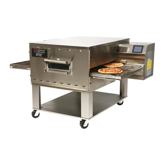
PS640 Series
Gas
Domestic & Std. Export
ENGLISH
PS640 Series Gas Ovens
Model:
•
PS640G Gas
OWNER'S OPERATING AND
INSTALLATION MANUAL
for domestic and standard export ovens
©2007 Middleby Marshall Inc.
is a registered trademark of Middleby Marshall, Inc. All rights reserved.
Middleby Cooking Systems Group • 1400 Toastmaster Drive • Elgin, IL 60120 • (847)741-3300 • FAX (847)741-4406
Combinations:
•
Single Oven
•
Double Oven (Two-Stack)
•
Triple Oven (Three-Stack)
P/N 60251
August 2007
Advertisement
Table of Contents

Related Manuals for Middleby Marshall PS640G


Summary of Contents for Middleby Marshall PS640G
- Page 1 INSTALLATION MANUAL for domestic and standard export ovens ©2007 Middleby Marshall Inc. is a registered trademark of Middleby Marshall, Inc. All rights reserved. Middleby Cooking Systems Group • 1400 Toastmaster Drive • Elgin, IL 60120 • (847)741-3300 • FAX (847)741-4406...
- Page 2 Installation section of this Manual. For domestic and standard export ovens, instructions are included in the Gas Conversion Kit. It is suggested to obtain a service contract with a Middleby Marshall Authorized Service Agent. WARNING POST, IN A PROMINENT LOCATION, THE EMERGENCY TELEPHONE NUMBER OF YOUR LOCAL GAS SUPPLIER AND INSTRUCTIONS TO BE FOLLOWED IN THE EVENT YOU SMELL GAS.
- Page 3 © 2003 - Middleby Marshall, A Middleby Company. The Middleby Marshall logo is a registered trademark of Middleby Marshall, A Middleby Company. Middleby Marshall Inc. • 1400 Toastmaster Drive • Elgin, Illinois 60120-9272 U.S.A. • (847) 741-3300 • FAX: (847) 741 4406...
-
Page 4: Table Of Contents
TABLE OF CONTENTS Page Page SECTION 1 – DESCRIPTION ..........1 OVEN USES ............1 SECTION 3 – OPERATION ..........14 LOCATION AND DESCRIPTION OF CONTROLS 16 II. OVEN COMPONENTS ..........1 A. Conveyor Motor Drive ........1 II. NORMAL OPERATION, STEP-BY-STEP ....17 B. -
Page 5: Section 1 – Description
SECTION 1 – DESCRIPTION Figure 1-1. Oven Components I. OVEN USES PS640 Series Ovens can be used to bake and/or cook a wide variety of food products, such as pizza, pizza –type products, cookies, sandwiches and others. II. OVEN COMPONENTS – see Figure 1-1. Conveyor Drive Motor: Moves the conveyor. - Page 6 Voltage Voltage Draw 208-240VAC 208-240VAC 50/60Hz 11-9.6 Amp 2 Pole 3 Wire (2 hot, 1 gd) Table 1-4: Gas orifice and pressure specifications for PS640G gas ovens Main Orifice I.D. Supply (Inlet) Orifice (Manifold) Bypass Type PS640G Pressure Pressure Pressure Natural 0.120...
-
Page 7: Section 2 – Installation
SECTION 2 – INSTALLATION WARNING – After any conversions, readjustments, or service work on the oven: • Perform a gas leak test. • Test for proper combustion and gas supply. • Test for correct air supply, particularly to the • Check that the ventilation system is in operation. burner blower. - Page 8 PS640 OVEN INSTALLATION REQUIRED KITS AND EQUIPMENT PS640 PS640 PS640 PS640 Gas Oven Single Oven DoubleOven TripleOven Installation Option Base w/ OptionBase w/ OptionBase w/ TYPE OF INSTALLATION 15″ Legs, 6″ Legs, Casters& Top Casters & Top Casters & Top P/N51100 P/N59720 P/N59725...
- Page 9 Figure 2-2. Model PS640 Single Oven Option Base with Legs and Top HARDWARE BAG 5, 6, 7, 10 & 11 PARTS LIST FOR PS640 SERIES SINGLE OVEN OPTION - BASE w/15″ ″ ″ ″ ″ LEGS & TOP P/N 59720 ITEM NO.
- Page 10 Figure 2-3. Model PS640 Double Oven Option Base with Legs and Top HARDWARE BAG 5, 6, 7, 10 & 11 PARTS LIST FOR PS640 SERIES DOUBLE OVEN OPTION - BASE w/6″ ″ ″ ″ ″ LEGS & TOP P/N 59725 ITEM NO.
- Page 11 Figure 2-4. Model PS640 Triple Oven Option Base with Outriggers and Top HARDWARE BAG 7, 8, 9, 10, 11, 12, 13, 14, & 17 PARTS LIST FOR PS640 SERIES TRIPLE OVEN OPTION - BASE w/CASTERS & TOP P/N 59726 ITEM NO. PART NO.
-
Page 12: Iii. Ventilation System
B. Recommendations III. VENTILATION SYSTEM NOTE THAT THE HOOD DIMENSIONS SHOWN IN F I G U R E 2 - 5 A R E R E C O M M E N D A T I O N S O N L Y . IMPORTANT LOCAL, NATIONAL AND INTERNATIONAL CODES M U S T B E F O L L O W E D W H E N I N S T A L L I N G T H E... -
Page 13: Iv. Assembly
Figure 2-6. Leg extension and casters installation IV. ASSEMBLY A. Top Panel and Base Pad Assembly Finished sides of leg extension face Install the four leg extensions onto the base pad using corner of base the 3/8″-16 × 1″ screws, 3/8″ flat washers, and 3/8″... -
Page 14: B. Stacking
For quad ovens, lock the two Gas oven cavities be stacked BY AUTHORIZED PERSONEL. front casters. Contact your Middleby Marshall Authorized Service Agent for Figure 2-10. Top panel installation complete stacking instructions. Stack an oven cavity on top of the lower oven. Check the following: #10-32 ×... -
Page 15: D. Conveyor Installation
D. Conveyor Installation Figure 2-13. Conveyor placement Unfold the conveyor as shown in Figure 2-12. Then, begin to slide the conveyor into the end of the oven. The conveyor can only be installed from the end of the oven with the drive motor. Crumb tray support Continue moving the conveyor into the oven until the... -
Page 16: Vi. Electrical Supply
If it is necessary to add or remove conveyor links to REVERSING THE CONVEYOR BELT achieve the correct tension, OR if it is necessary to Remove the conveyor from the oven and find the master link reverse the conveyor belt for correct orientation, the belt location. -
Page 17: Connection
The terms of the oven’s warranty require all start-ups, conversions and service work to be Gas Meter performed by a Middleby Marshall Authorized • One or two cavities: 750 cfh meter Service Agent. • Three oven cavities: 1200 cfh meter Gas Line •... -
Page 18: B. Connection
B. Connection Figure 2-18. Flexible Gas Hose Installation Check the oven’s gas supply requirements before making the gas utility connection. Gas supply requirement are listed on the oven’s serial plate and in Table 1-4. Gas Orifice and Pressure Specifications (in Section 1, Description). 1/2″... -
Page 19: F. Adjusting The Minimum Pressure Setting
Figure 2-20. Burner Assembly Adjusting the Minimum Pressure Setting Disconnect pressure feedback connection (if appcable). Connect a suitable pressure gauge to pipe line or to outlet pressure tap of gas control concerned, to measure burner Valve pressure (measuring point must be as near to burner as possible). - Page 20 SECTION 3 - OPERATION C. Temperature Control Display E. Message Bar Increase Decrease A. Main On/Off Button B. Conveyor Time Setting D. TEMP Set Right Left LOCATION AND DESCRIPTION OF CONTROLS C. Temperature Control/Display A. Main On/Off Button Displays the set point of the oven. Turns all oven functions on or off.
-
Page 21: A. Main Screen
NORMAL OPERATION - STEP-BY-STEP Push the “ON/OFF” button to start the oven. The con- A. Main Screen troller will display the screen, as shown in Figure 3-3. When the unit has been “OFF” for more than 1 minute the controller will display the screen saver, as shown in Figure 3-3 Main Screen ON Figure 3-1. -
Page 22: B. Daily Startup Procedure
To change the conveyor belt speed, push the “TIME” C. Daily Shutdown Procedure button. The controller will display the screen, shown in Make certain there are no products left on the conveyor in Figure 3-5. To change the minute setting, push the “← ← ← ← ← ” the oven. -
Page 23: Iii. Quick Reference: Troubleshooting
III. QUICK REFERENCE: TROUBLESHOOTING SYMPTOM PROBLEM SOLUTION Oven will not No electrical power • Check that the circuit breaker/fused disconnect is on. turn On. Make sure the emergenct stop button is on. Oven will not No gas pressure • Make sure main gas is on. heat. -
Page 24: Section 4 – Maintenance
NOTE ANY replacement parts that require access to the interior of the oven may ONLY be replaced by a Middleby Marshall Authorized Service Agent. It is also strongly recommended that the 3-Month Maintenance and 6-Month Maintenance procedures in this section be performed ONLY by a Middleby Marshall Authorized Service Agent. -
Page 25: Ii. Maintenance – Monthly
Figure 4-2. Removing Air Fingers and Plates II. MAINTENANCE – MONTHLY NOTE: When removing the conveyor, refer to Figure 2-12 (in Section 2, Installation). A. Check that the oven is cool and the power is disconnected, as described in the warning at the beginning of this Section. B. -
Page 26: Iii. Maintenance – Every 3 Months
Reassemble the idler shaft into the conveyor. Make III. MAINTENANCE – EVERY 3 MONTHS sure that the bronze washer is in place between the A. Check that the oven is cool and the power is discon- two sections of the shaft. See Figure 4-4. nected, as described in the warning at the beginning of Replace the conveyor adjustment screws as shown in this Section. -
Page 27: Iv. Maintenance – Every 6 Months
Figure 4-7. Rear panel access Figure 4-6. Disassembling the drive shaft Remove eight (8) screws to remove rear panel Bearings (2 total) Grease fitting (1 per bearing) Blower belt Blower motor Loosen four (4) screws to adjust motor position and belt tension IV. - Page 28 V. KEY SPARE PARTS – Available separately. See Figure 4-8. 16, 17, 18 Figure 4-8. Key Spare Parts KEY SPARE PARTS PS640 GAS (B & W Touchscreen) ITEM QTY. DESCRIPTION 60191 Digital Display, Programmed 58920 Motor, Conveyor Drive 58679 Conveyor Control Board 60192 Inverter, Programmed M9608...
- Page 29 SECTION 5 - WIRING DIAGRAM...
- Page 30 NOTES...
- Page 31 NOTES...
- Page 32 NOTICE During the warranty period, ALL parts replacement and servicing should be performed by your Middleby Marshall Authorized Service Agent. Service that is performed by parties other than your Middleby Marshall Authorized Service Agent may void your warranty.
Need help?
Do you have a question about the PS640G and is the answer not in the manual?
Questions and answers