Table of Contents
Advertisement
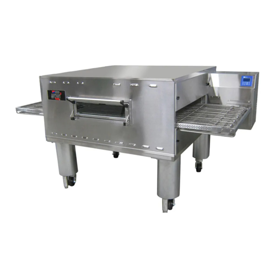
PS638 Series
Electric and Gas Oven
Domestic & Standard Export
rd
Released October 3
, 2017
PS638 Series Electric and Gas Ovens
Model:
PS638E Electric
PS638G Gas
OWNER'S OPERATING AND
INSTALLATION MANUAL
f o r D o m e s t i c & S t a n d a r d E x p o r t O v e n s
© 2019 Middleby Marshall Inc.
is a registered trademark of Middleby Marshall, Inc. All rights reserved.
Combinations:
Single Oven
Double Oven (Two-Stack)
Triple Oven (Three-Stack)
KOF Applications
P/N: 74617
Revision D
Sep
st
tember 1
, 2019
ENGLISH
Advertisement
Table of Contents


Need help?
Do you have a question about the PS638 Series and is the answer not in the manual?
Questions and answers