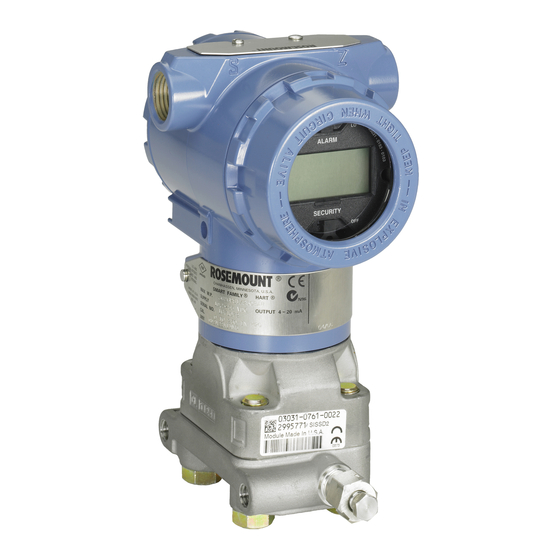
Emerson Rosemount 3051 Quick Start Manual
Pressure transmitter, dp flow meter
Hide thumbs
Also See for Rosemount 3051:
- Quick start manual ,
- Reference manual (222 pages) ,
- Manual (127 pages)

Related Manuals for Emerson Rosemount 3051


Summary of Contents for Emerson Rosemount 3051
- Page 1 Quick Start Guide 00825-0100-4100, Rev FA December 2019 ™ Rosemount 3051 Pressure Transmitter and Rosemount 3051CF DP Flow Meters ® with WirelessHART Protocol...
- Page 2 Safety Messages NOTICE This guide provides basic guidelines for Rosemount 3051 Wireless Transmitters. It does not provide instructions for configuration, diagnostics, maintenance, service, troubleshooting or Intrinsically Safe (I.S.) installations. Refer to the for more instruction. This manual is also available electronically on Emerson.com/Rosemount.
-
Page 3: Wireless Considerations
Power up sequence The power module should not be installed on any wireless device until the Emerson Wireless Gateway (Gateway) is installed and functioning properly. This transmitter uses the green power module (order model number 701PGNKF). Wireless devices should also be powered up in order of proximity from the Gateway, beginning with the closest. -
Page 4: Transmitter Installation
Quick Start Guide December 2019 Transmitter installation Mount the transmitter Figure 2-1: Panel Mount Coplanar Flange 5/16 x 1½ panel bolts are customer supplied. Figure 2-2: Pipe Mount Coplanar Flange Emerson.com/Rosemount... - Page 5 December 2019 Quick Start Guide Figure 2-3: Panel Mount Traditional Flange Figure 2-4: Pipe Mount Traditional Flange Figure 2-5: Panel Mount Rosemount 3051T Quick Start Guide...
- Page 6 Quick Start Guide December 2019 Figure 2-6: Pipe Mount Rosemount 3051T Emerson.com/Rosemount...
- Page 7 December 2019 Quick Start Guide 2.1.1 Mount the transmitter in liquid applications Procedure 1. Place taps to the side of the line. 2. Mount beside or below the taps. 3. Mount the transmitter so the drain/vent valves are oriented upward. Figure 2-7: Mounting the Transmitter in Liquid Applications In-line 2.1.2...
- Page 8 If the transmitter installation requires assembly of the process flanges, manifolds, or flange adapters, follow the assembly guidelines to ensure a tight seal for optimal performance characteristics of the transmitters. Use only bolts supplied with the transmitter or sold by Emerson as spare parts. Figure 2-10 illustrates common transmitter assemblies with the bolt length required for proper transmitter assembly.
- Page 9 2-1. If bolt material is not shown in Table 2-1, contact a local Emerson representative for more information. Carbon steel bolts do not require lubrication, and the stainless steel bolts are coated with a lubricant to ease installation. However, do not apply additional lubricant when installing either type of bolt.
- Page 10 Whenever the flanges or adapters are removed, visually inspect the O-rings. Replace them if there are any signs of damage, such as nicks or cuts. If you replace the O-rings, re-torque the flange bolts and alignment screws after installation to compensate for seating of the PTFE O-ring. Emerson.com/Rosemount...
- Page 11 December 2019 Quick Start Guide 2.1.6 Environmental seal for housing ® For NEMA 4X, IP66, and IP68 requirements, use thread sealing (PTFE) tape or paste on male threads of conduit to provide a water and dust tight seal. Consult factory if other ingress protection ratings are required. For M20 threads, install conduit plugs to full thread engagement or until mechanical resistance is met.
- Page 12 4. Retighten the housing rotation set screw to no more than 7 in-lb when it reaches the desired location. Connect the power module Procedure 1. Remove the power module cover. 2. Connect the green power module (see Figure 2-14). Emerson.com/Rosemount...
- Page 13 A zero trim can be performed using either a Field Communicator or configuration buttons. For instructions using AMS Wireless Configurator, see the Rosemount 3051 Wireless Reference Manual.
- Page 14 Via the Emerson Wireless Gateway’s integrated web interface. • Via AMS Wireless Configurator. 2.5.1 Verify transmitter configuration using LCD display The LCD display will show the output values at the same rate as the wireless update rate. Refer to the Rosemount 3051 Wireless Reference Manual Emerson.com/Rosemount...
- Page 15 N E G O T L I M - O P 2.5.2 Verify transmitter configuration using Field Communicator For HART Wireless transmitter communication, a Rosemount 3051 Wireless device descriptor is required. For connecting with a Field Communicator, refer to Figure 1-1.
- Page 16 Simulate Digital Signal 3, 6 2.5.3 Verify transmitter configuration using Emerson Wireless Gateway In the Gateway’s integrated web interface, navigate to the Explorer > Status page. This page will show whether the device has joined the network and if it is communicating properly.
- Page 17 December 2019 Quick Start Guide 2.5.4 Verifying configuration using AMS Wireless Configurator When the device has joined the network, it will appear in the AMS Wireless Configurator as shown in Figure 2-17. Figure 2-17: Wireless Configurator Network Setup Quick Start Guide...
-
Page 18: Troubleshooting
If the device has not joined to the network after power up, verify the correct configuration of the network ID and join key. Verify that active advertising has been enabled on the Emerson Wireless Gateway. The network ID and join key in the device must match the network ID and join key of the Gateway. -
Page 19: Product Certifications
RF spectrum. Nearly every country requires this type of product certification. Emerson is working with governmental agencies around the world to supply fully compliant products and remove the risk of violating country directives or laws governing wireless device usage. - Page 20 T4(–40 °C ≤ T ≤ +70 °C) when installed per Rosemount drawing 03031-1062; Type 4X/IP66/IP68 Special Conditions for Safe Use (X): 1. The Rosemount 3051 Wireless Pressure Transmitter shall only be ™ used with the 701PGNKF Rosemount SmartPower Battery Pack.
- Page 21 1. The plastic enclosure may constitute a potential electrostatic ignition risk and must not be rubbed or cleaned with a dry cloth. 2. The Emerson 701PGNKF Power Module may be replaced in a hazardous area. The power module has a surface resistivity greater than 1 GΩ...
- Page 22 Special Conditions for Safe Use (X): See certificate for special conditions. 4.5.9 Korea IP Korea Intrinsic Safety Certificate 13-KB4BO-0295X Markings Ex ia IIC T4 (–40 °C ≤ T ≤ +70 °C) Special Conditions for Safe Use (X): See certificate for special conditions. Emerson.com/Rosemount...
- Page 23 December 2019 Quick Start Guide 4.5.10 Additional Certifications SBS American Bureau of Shipping (ABS) Type Approval Certificate 15-HS1405241-PDA Intended Use Marine & Offshore Applications - Measurement of either gauge or absolute pressure for liquid, gas and vapor. SBV Bureau Veritas (BV) Type Approval Certificate 23155 Requirements Bureau Veritas Rules for the Classification of Steel Ships...
- Page 24 Quick Start Guide December 2019 Declaration of Conformity Emerson.com/Rosemount...
- Page 25 December 2019 Quick Start Guide Quick Start Guide...
- Page 26 Quick Start Guide December 2019 Emerson.com/Rosemount...
- Page 27 December 2019 Quick Start Guide Quick Start Guide...
- Page 28 The Emerson logo is a Twitter.com/Rosemount_News trademark and service mark of Emerson Electric Facebook.com/Rosemount Co. Rosemount is a mark of one of the Emerson Youtube.com/user/ family of companies. All other marks are the RosemountMeasurement property of their respective owners.
Need help?
Do you have a question about the Rosemount 3051 and is the answer not in the manual?
Questions and answers