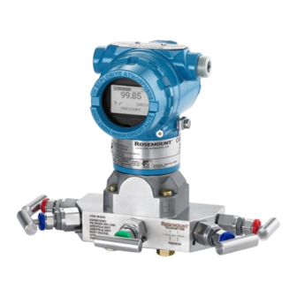
Emerson Rosemount 3051 Operating Instructions Manual
Pressure transmitter
Hide thumbs
Also See for Rosemount 3051:
- Quick start manual ,
- Reference manual (222 pages) ,
- Manual (127 pages)

Related Manuals for Emerson Rosemount 3051


Summary of Contents for Emerson Rosemount 3051
- Page 1 Quick Start Guide 00825-0100-4007, Rev HG December 2023 Rosemount 3051 Pressure ™ Transmitter and 3051CF Series Flow Meter with 4-20 mA HART ®...
-
Page 2: Table Of Contents
Quick Start Guide December 2023 Contents About this guide........................... 3 Mounting the transmitter......................5 Rotate housing........................... 13 Set the switches......................... 14 Connect the wiring and power up................... 16 Verify configuration parameters....................21 Trimming the transmitter......................25 Safety Instrumented Systems (SIS)..................27 Product certifications........................ 28 Emerson.com... -
Page 3: About This Guide
December 2023 Quick Start Guide 1 About this guide This guide provides basic guidelines for Rosemount 3051 Transmitters. It does not provide instructions for configuration, diagnostics, maintenance, service, troubleshooting, explosion-proof, flameproof, or Intrinsically Safe (IS) installations. Refer to the Rosemount 3051 Pressure Transmitter Manual for more instructions. - Page 4 M20 × 1.5 thread form. On devices with multiple conduit entries, all entries will have the same thread form. When installing in a hazardous location, use only appropriately listed or Ex certified plugs, glands, or adapters in cable/conduit entries. Emerson.com...
-
Page 5: Mounting The Transmitter
December 2023 Quick Start Guide 2 Mounting the transmitter WARNING Process connection temperatures above +185 °F (+85 °C) require a limited ambient temperature, reduced by a 1:1.5 ratio. Consider process connection and ambient temperatures when installing the 3051 with hazardous location certifications. See Table 2-1. - Page 6 2.2 Mount the transmitter in a gas flow application NOTICE A bracket is required to support the transmitter and the ¼-inch tubing going into the transmitter. Procedure 1. Place taps in the top or side of the line. Emerson.com...
- Page 7 December 2023 Quick Start Guide 2. Mount the transmitter beside or above the taps. 2.3 Steam flow applications Procedure 1. Place taps to the side of the line. 2. Mount beside or below the taps. 3. Fill impulse lines with water. Quick Start Guide...
- Page 8 Quick Start Guide December 2023 2.4 Panel and pipe mount Figure 2-1: Panel and Pipe Mounting Panel mount Pipe mount Coplanar flange Traditional flange Rosemount 3051T Rosemount 3051H 5/16 x 1½ panel bolts are customer supplied. Emerson.com...
- Page 9 Use only bolts supplied with the transmitter or sold by Emerson as spare parts. Figure 2-2 illustrates common transmitter assemblies with the bolt length required for proper transmitter assembly.
- Page 10 Failure to install proper flange adapter O-rings may cause process leaks, which can result in death or serious injury. The two flange adapters are distinguished by unique O-ring grooves. Only use the O-ring that is designed for its specific flange adapter, as shown in Figure 2-3. Emerson.com...
- Page 11 December 2023 Quick Start Guide Figure 2-3: O-ring location Rosemount 3051S/3051/2051 A. Flange adapter B. O-ring C. PFTE-based profile (square) D. Elastomer profile (round) Note Whenever the flanges or adapters are removed, visually inspect the O-rings. Replace them if there are any signs of damage, such as nicks or cuts.
- Page 12 Quick Start Guide December 2023 Figure 2-4: In-line gauge low side pressure port A. Pressure port location Emerson.com...
-
Page 13: Rotate Housing
December 2023 Quick Start Guide 3 Rotate housing To improve field access to wiring or to better view the optional display: Procedure 1. Loosen the housing rotation set screw using a 5/64-inch hex wrench. 2. Turn the housing left or right up to a maximum of 180° from its original position. -
Page 14: Set The Switches
2. Remove the housing cover opposite the field terminal side. WARNING Do not remove the instrument cover in explosive atmospheres when the circuit is live. 3. Slide the Security and Alarm switches into the preferred position using a small screwdriver. Emerson.com... - Page 15 December 2023 Quick Start Guide 4. Reattach the transmitter cover. WARNING The cover must be fully engaged to comply with explosion- proof requirements. Quick Start Guide...
-
Page 16: Connect The Wiring And Power Up
Quick Start Guide December 2023 5 Connect the wiring and power up Figure 5-1 shows wiring connections necessary to power a Rosemount 3051 Transmitter and enable communications with a communication device. Figure 5-1: Transmitter wiring diagrams A. Power supply B. Ground C. Resistor... - Page 17 When using a direct wiring method, wrap wire clockwise to ensure it is in place when tightening the terminal block screw. NOTICE Emerson does not recommend using a pin or a ferrule wire, as the connection may be more susceptible to loosening over time or under vibration.
- Page 18 2. Connect the wiring pair and ground as indicated in Figure 5-2. Make sure the wiring is: • Trimmed close and insulated from touching the transmitter housing • Continuously connected to the termination point • Connected to a good earth ground at the power supply end Emerson.com...
- Page 19 The transmitter must have a minimum of 250 Ω to communicate with a communication device. If you are using a single power supply to power more than one Rosemount 3051 Transmitter, ensure the power supply used and the circuitry common to the transmitters do not have more than 20 Ω...
- Page 20 The total resistance load is the sum of the resistance of the signal leads and the load resistance of the controller, indicator, intrinsically safe (IS) barriers, and related pieces. If you use IS barriers, then include the resistance and voltage drop. Emerson.com...
-
Page 21: Verify Configuration Parameters
Transfer function • Units Figure 6-1 for a full menu tree. NOTICE Emerson recommends installing the latest device descriptor (DD) to ensure full functionality. Download the latest DD at Software & Drivers. Procedure 1. Set alarm and saturation values: Device Settings → Setup Overview → Alarm and Saturation Values. - Page 22 Quick Start Guide December 2023 • Other units: Device Settings → Output → Pressure/Flow/ Totalizer/Level/Volume/Module Temperature → Setup Figure 6-1: DD menu tree 6.1 Wireless configuration via Bluetooth technology ® 6.1.1 Download AMS Device Configurator Procedure Download and install the app from your app store. Emerson.com...
- Page 23 ® Procedure 1. Launch AMS Device Configurator. AMS Device Configurator for Emerson Field Devices. 2. Select the device where you want to connect. 3. On first connection, enter the key for selected device. 4. At the top left, select the menu icon to navigate the desired device menu.
- Page 24 December 2023 Bluetooth UID and key ® You can find the Unique Identifier (UID) and key on the disposable paper tag attached to: • The device • The terminal block cover • The display unit Figure 6-2: Bluetooth security information Emerson.com...
-
Page 25: Trimming The Transmitter
Quick Start Guide 7 Trimming the transmitter Note Emerson ships transmitters fully calibrated per request or by the factory default of full scale (span = upper range limit). 7.1 Zero trim A zero trim is a single-point adjustment used for compensating mounting position effects. - Page 26 2. Set the 4 mA point by pressing the Zero button for two seconds. Verify the output is 4 mA. The optional LCD display will show ZERO PASS Figure 7-1: Zero adjustment or Quick Service buttons Emerson.com...
-
Page 27: Safety Instrumented Systems (Sis)
December 2023 Quick Start Guide 8 Safety Instrumented Systems (SIS) For safety certified installations, refer to the Rosemount 3051 Pressure Transmitter Manual for installation procedure and system requirements. Quick Start Guide... -
Page 28: Product Certifications
A copy of the EU Declaration of Conformity can be found at the end of the Quick Start Guide. The most recent revision of the EU Declaration of Conformity can be found at Emerson.com. 9.2 Federal Communication Commission (FCC) notice This device complies with Part 15 of the Federal Communication Commission Rules. - Page 29 December 2023 Quick Start Guide Laboratory (NRTL) as accredited by the Federal Occupational Safety and Health Administration (OSHA). 9.5 North America 9.5.1 E5 USA Explosion-proof (XP) and Dust-Ignition-proof (DIP) FM16US0121 Certificate Range 1-5 (HART only) ® FM 3600: 2018, FM 3615: 2018, FM 3616: 2011, FM 3810: Standards 2005, ANSI/NEMA 250: 2008...
- Page 30 Care must be taken into account during installation and use to prevent impact and friction. 2. The Rosemount 3051 Transmitter with the transient terminal block (option code ) will not pass the 500 Vrms dielectric strength test, and this must be taken into account during installation.
- Page 31 Care must be taken into account during installation and use to prevent impact and friction. 2. The Rosemount 3051 Transmitter with the transient terminal block (option code ) will not pass the 500 Vrms dielectric strength test, and this must be taken into account during installation.
- Page 32 Type 4X, IP 68 Install per 03031-1024. Specific Conditions for Use 1. The Rosemount 3051 Transmitter housing contains aluminum and is considered a potential risk of ignition by impact or friction. Care must be taken into account during installation and use to prevent impact and friction.
- Page 33 2. Equipment evaluated for atmospheric pressure range between 80 kPa (0.8 bar) to 110 kPa (1.1 bar). 3. The Rosemount 3051 Transmitter with the transient terminal block (option code ) will not pass the 500 Vrms dielectric strength test, and this must be taken into account during installation.
- Page 34 3. Non-standard paint options may cause risk from electrostatic discharge. Avoid installations that could cause electrostatic build-up on painted surfaces and only clean the painted surfaces with a damp cloth. If paint is ordered through a special option code, contact the manufacturer for more information. Emerson.com...
- Page 35 December 2023 Quick Start Guide 4. Some variants of the equipment have reduced markings on the nameplate. Refer to the Certificate for full equipment marking. 5. Variants with a paint finish must not be installed in a dust- laden airflow. 9.6.2 I1 ATEX Intrinsic Safety and Dust BAS97ATEX1089X;...
- Page 36 EN IEC 60079-0: 2018, EN60079-15: 2010, EN60079-31: Standards 2014 Markings II 3 G Ex nA IIC T5 Gc –40 °C ≤ T ≤ +70 °C; II 1 D Ex ta IIIC T 105 °C Da –20 °C ≤ T ≤ +85 °C Emerson.com...
- Page 37 December 2023 Quick Start Guide Specific Conditions for Safe Use (X): 1. The apparatus is not capable of withstanding the 500 V insulation test required by EN 60079-15: 2010. This must be taken into account when installing the apparatus. 2. The enclosure may be made of aluminum alloy and given a protective polyurethane paint finish;...
- Page 38 2. The enclosure may be made of aluminum alloy and given a protective polyurethane paint finish; however, care should be taken to protect it from impact or abrasion if located in Zone 0. Emerson.com...
- Page 39 December 2023 Quick Start Guide IECEx Mining (Special A0259) IECEx TSA 14.0001X Certificate IEC 60079-0 :2011, IEC 60079-11: 2011 Standards Ex ia I Ma (–60 °C ≤ T ≤ +70 °C) Markings Table 9-6: Input parameters HART Fieldbus/ FISCO PROFIBUS Voltage U 30 V 30 V 17.5 V...
- Page 40 1. This device contains a thin wall diaphragm with less than 1 mm thickness that forms a boundary between zone 0 (process connection) and zone 1 (all other parts of the equipment). The model code and datasheet are to be consulted for details Emerson.com...
- Page 41 December 2023 Quick Start Guide of the diaphragm material. Installation, maintenance, and use shall take into account the environmental conditions to which the diaphragm will be subjected. The manufacturer's instructions for installation and maintenance shall be followed in detail to assure safety during its expected lifetime. 2.
- Page 42 3051 Series: Ex db IIC T6···T4 Ga/Gb, Ex ta IIIC T200 Markings 105 °C Da (-20 °C ≤ Ta ≤ 85 °C) 3051CF Series: Ex d IIC T6~T4 Ga/Gb 9.9.2 I3 China Intrinsic Safety GYJ23.1139X; GYJ20.1488X [Flow meters] Certificate GB/T 3836.1-2021, GB/T 3836.4-2021, GB/T 3836.31-2021 Standards Emerson.com...
- Page 43 December 2023 Quick Start Guide 3051 Series: Ex ia IIC T4 Ga, Ex ta IIIC T500 105 °C Da Markings 3051CF Series: Ex ia IIC T4 Ga, Ex ta IIIC T500 105 °C Da 9.9.3 N3 China Type n GYJ20.1110X Certificate GB/T 3836.1-2021, GB/T 3836.3-2021 Standards Ex ec IIC T5 Gc...
- Page 44 Combination of C6, E8, and I1 Combination of E7, I7, and N7 Combination of E8, I1, and N1 Combination of E5, I5, and C6 Combination of E8, I1, E5, I5, and C6 Combination of EM and IM Combination of EP and IP Emerson.com...
- Page 45 December 2023 Quick Start Guide 9.14 Additional certifications 9.14.1 SBS American Bureau of Shipping (ABS) Type Approval Certificate 18-HS1814795-PDA Marine and offshore applications – Measurement of Intended use either gauge or absolute pressure for liquid, gas, and vapor. 9.14.2 SBV Bureau Veritas (BV) Type Approval 23155 Certificate Bureau Veritas rules for the classification of steel...
- Page 46 Quick Start Guide December 2023 9.15 EU Declaration of Conformity Emerson.com...
- Page 47 December 2023 Quick Start Guide Quick Start Guide...
- Page 48 Quick Start Guide December 2023 Emerson.com...
- Page 49 December 2023 Quick Start Guide Quick Start Guide...
- Page 50 Quick Start Guide December 2023 9.16 China RoHS Emerson.com...
- Page 51 December 2023 Quick Start Guide Quick Start Guide...
- Page 52 2023 Emerson. All rights reserved. Emerson Terms and Conditions of Sale are available upon request. The Emerson logo is a trademark and service mark of Emerson Electric Co. Rosemount is a mark of one of the Emerson family of companies. All other marks are the property of their respective owners.
Need help?
Do you have a question about the Rosemount 3051 and is the answer not in the manual?
Questions and answers