Penn A421 Series Installation Manual
Electronic temperature controls with cycle timer
Hide thumbs
Also See for A421 Series:
- Installation manual (29 pages) ,
- Installation instructions manual (20 pages) ,
- Installation manual (15 pages)
Table of Contents
Advertisement
Quick Links
Applications
Important: Use this A421 Series Electronic
Temperature Control only as an operating control.
Where failure or malfunction of the A421 Control
could lead to personal injury or property damage
to the controlled equipment or other property,
additional precautions must be designed into the
control system. Incorporate and maintain other
devices, such as supervisory or alarm systems or
safety or limit controls, intended to warn of or
protect against failure or malfunction of the A421
Control.
Important: Utiliser ce A421 Series Electronic
Temperature Control uniquement en tant que
dispositif de régulation. Lorsqu'une défaillance
ou un dysfonctionnement du A421 Control risque
de provoquer des blessures ou d'endommager
l'équipement contrôlé ou un autre équipement, la
conception du système de contrôle doit intégrer des
dispositifs de protection supplémentaires. Veiller
dans ce cas à intégrer de façon permanente d'autres
dispositifs, tels que des systèmes de supervision
ou d'alarme, ou des dispositifs de sécurité ou de
limitation, ayant une fonction d'avertissement
ou de protection en cas de défaillance ou de
dysfonctionnement du A421 Control.
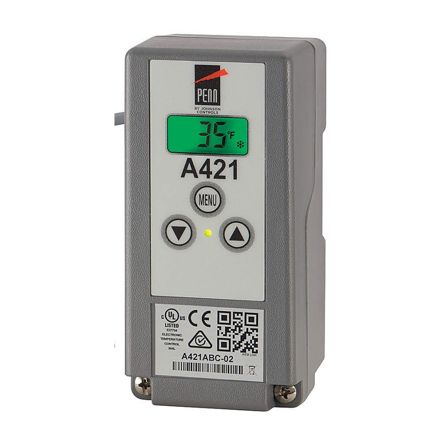
The A421 Series Electronic Temperature Controls are
single-stage, electronic temperature controls with a single-
pole, double-throw (SPDT) output relay.
A421 Controls feature a backlit LCD with adjustable
brightness and three-button touchpad interface that can
be set up to restrict user adjustments. An LED indicates
the output relay's on and off status.
A421 Control with Cycle Timer also provides sensor
offset capability and restricted user adjustment. The
temperature control range is -40°F to 212°F or -40°C to
100°C.
The A421 Controls are available either in Type 1 (NEMA),
IP20 (CE), high-impact plastic enclosures suitable for
surface or DIN rail mounting (Figure 1) or in Type 4X
(NEMA), IP66 (CE) watertight, corrosion resistant surface
mount enclosures (Figure 2).
The control housing base on the Type 4X/IP66 models can
be easily rotated 180º relative to the control housing cover
and LCD, allowing you to bring the electrical connection to
either the top or bottom of the mounted control. Do not
twist the wiring harness between the housing base and
cover more than 180º.
A421 Series Electronic Temperature Controls
with Cycle Timer Installation Guide
Dimensions
Figure 1: A421ABT Control with Type 1 (NEMA), IP20
enclosure; dimensions, in. (mm)
Figure 2: A421AET Control with Type 4X (NEMA), IP66
enclosure; dimensions, in. (mm)
Part No. 24-7664-3043 Rev. C
2018-11-13
A421ABT, A421AET
Advertisement
Table of Contents

Related Manuals for Penn A421 Series


Summary of Contents for Penn A421 Series
- Page 1 A421 Control. The A421 Series Electronic Temperature Controls are single-stage, electronic temperature controls with a single- pole, double-throw (SPDT) output relay. A421 Controls feature a backlit LCD with adjustable brightness and three-button touchpad interface that can be set up to restrict user adjustments.
- Page 2 Control includes an A99 sensor. Any A99 Series sensor • Do not mount the control on surfaces that are prone works with the A421 Series Controls. Do not replace an to vibration or in a location where high-voltage relays, A99 Series sensor with any other brand, series, or type motor starters, other sources of electromagnetic of temperature sensor.
- Page 3 Disconnect or isolate all power supplies before mak- Observe the following guidelines, procedures, and ing electrical connections. More than one disconnec- illustrations when you wire an A421 Series control and A99 tion or isolation may be required to completely de-en- Series sensor.
- Page 4 Normal control resumes shielded after this switch is opened again. cable COM Connects the low-voltage common from the sensor and binary input. Connects the low-voltage input signal wire from control sensors. A421 Series Electronic Temperature Controls with Cycle Timer Installation Guide...
-
Page 5: Setup And Adjustments
Low Temperature Stop (LtS) The A421 Series Control has a backlit LCD screen (Figure 5). You can adjust the LCD brightness. During normal Select the lowest temperature value below operation, the LCD displays the Main screen, which... - Page 6 30 seconds, the main screen is displayed setting and the backlight setting returns to the selected brightness level. The default values for general application models are shown. OEM models may have different default values. A421 Series Electronic Temperature Controls with Cycle Timer Installation Guide...
- Page 7 • Temperature Units (Un) • Low Temperature Stop (LtS) • High Temperature Stop (HtS) • Low Temperature On-Time (Ltt) • Minimum Relay On-Time (Ont) • Cycle Period (cP) A421 Series Electronic Temperature Controls with Cycle Timer Installation Guide...
- Page 8 • The Ltt is the minimum time required to ventilate the To scroll through all of the advanced parameter codes and display the preferred code, press Down or controlled space. A421 Series Electronic Temperature Controls with Cycle Timer Installation Guide...
- Page 9 (by over-adjusting the On value or OFF value). A421 Series Electronic Temperature Controls with Cycle Timer Installation Guide...
-
Page 10: Troubleshooting Procedure
Troubleshooting If the measured values conform to the values in Figure 12, proceed to Step 3. A421 Series Controls display fault codes on the LCD as g. If the sensor’s measured resistance value is described in Table 4. substantially different from the expected value for that temperature, check the sensor wiring. -
Page 11: Repair Information
PTC Temperature Sensor: Standard probe 2 in. A99BC-100C (5.1 cm) with 3.3 ft (1.0 m) high-temperature See Table 5 to order a standard A421 Series Electronic silicon cable; ambient operating temperature Temperature Control. See Table 6 and Table 7 for range: -40ºF to 212ºF (-40ºC to 100ºC) -
Page 12: Technical Specifications
125 (125) 125 (125) consumption (LC/LNC) Supply power 110/120 or 208/230/240 VAC, 50/60 Hz Table 10: UL conformity declaration information Information Description Purpose of control Sensing control / Operating control A421 Series Electronic Temperature Controls with Cycle Timer Installation Guide... -
Page 13: North American Emissions Compliance
This Class (B) digital apparatus meets all the requirements of the Canadian Interference-Causing Equipment Regulations. Cet appareil numérique de la Classe (B) respecte toutes les exigences du Règlement sur le matériel brouilleur du Canada. A421 Series Electronic Temperature Controls with Cycle Timer Installation Guide... - Page 14 Single point of contact APAC Europe NA/SA JOHNSON CONTROLS JOHNSON CONTROLS JOHNSON CONTROLS C/O CONTROLS PRODUCT WESTENDHOF 3 507 E MICHIGAN ST MANAGEMENT 45143 ESSEN MILWAUKEE WI 53202 NO. 32 CHANGJIJANG RD NEW GERMANY DISTRICT WUXI JIANGSU PROVINCE 214028 CHINA For more contact information, refer to www.johnsoncontrols.com/locations.
Need help?
Do you have a question about the A421 Series and is the answer not in the manual?
Questions and answers