Table of Contents
Advertisement
Available languages
Available languages
Quick Links
Advertisement
Table of Contents

Related Manuals for Ingersoll-Rand ELB2612N


Summary of Contents for Ingersoll-Rand ELB2612N
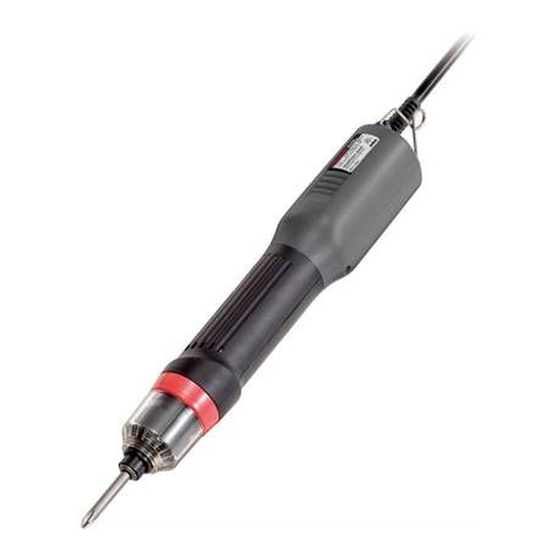
- Page 1 45549110 Edition 1 April 2008 Brushless Electric Screwdrivers Models ELB2612N, ELB2620N, EPB2612N and EPB2620N Product Information Product Information Especificaciones del producto Spécifications du produit Save These Instructions...
-
Page 2: Product Safety Information
High Machine Tapping Torque Torque Screw Screw Spring Spring 115 AC, ELB2612N 0.4 ~ 1.6 1.2 ~ 3.0 1,200 2.6 ~ 5.0 2.5 ~ 4.0 50/60 Hz 115 AC, ELB2620N 0.4 ~ 1.6 1.2 ~ 3.0 2,000 2.6 ~ 5.0 2.5 ~ 4.0... -
Page 3: Torque Adjustment
Attaching and Detaching a Bit Pulling the holder clamp in the direction of the arrow unlocks it. You can then attach or detach a bit. Holder Clamp (Dwg. 45595618-1) Torque Adjustment To adjust the torque, detach torque adjustment ring cover and adjust the torque adjustment ring clockwise for higher torque or counter-clockwise for lower torque. - Page 4 High Torque Spring Low Torque Spring (Accessories) 1 2 3 4 5 6 7 8 9 Torque Scale (Dwg. 45595618-4) The spring can be easily replaced by removing the torque adjustment ring cover and the torque adjustment ring at the end of the tool. When replacing the spring, apply grease evenly around the outside of the spring.
-
Page 5: Grounding Instructions
Grounding Instructions The tool should be grounded while in use to protect the operator from electric shock. The tool is equipped with a three-conductor cord and three-prong grounding-type plug to fit the proper grounding-type receptacle. The green (or green and yellow) conductor in the cord is the grounding wire. - Page 6 Muelle Tornillo de Tornillo de de Par de de Par de Máquina Golpeteo Apriete Apriete 115 CA, ELB2612N 0.4 ~ 1.6 1.2 ~ 3.0 1,200 2.6 ~ 5.0 2.5 ~ 4.0 50/60 Hz 115 CA, ELB2620N 0.4 ~ 1.6 1.2 ~ 3.0 2,000 2.6 ~ 5.0...
- Page 7 Poner y Quitar Puntas Tirar del gancho del soporte en la dirección de la flecha hace que se desbloquee. Entonces puede poner o quitar la punta. Abrazadera del soporte (Dibujo. 45595618-1) Ajuste de Par Para ajustar el par, quite la tapa de la anilla para ajuste de par y ajuste la anilla de par en el sentido horario para un mayor par o en el antihorario para un menor apriete.
- Page 8 Muelle de par alto Muelle de par bajo (Accesorios) 1 2 3 4 5 6 7 8 9 Escala del par (Dibujo. 45595618-4) El muelle se puede sustituir fácilmente quitando la tapa de la anilla para ajuste del par y la anilla para ajuste del par del extremo de la herramienta.
-
Page 9: Piezas Y Mantenimiento
Instrucciones de Toma de Tierra La herramienta debe tener una toma de tierra mientras está en uso para proteger al operario de un cortocircuito eléctrico. La herramienta está equipada con un cable conductor de tres hilos y con un enchufe de tipo toma de tierra con tres tomas para adaptarse al receptáculo de toma adecuado. -
Page 10: Informations Relatives À La Sécurité Du Produit
Modèles Ressort Ressort de Couple de Couple tr/min Machine Taraudeuse Minimum Maximum 115 c.a., ELB2612N 0.4 ~ 1.6 1.2 ~ 3.0 1,200 2.6 ~ 5.0 2.5 ~ 4.0 50/60 Hz 115 c.a., ELB2620N 0.4 ~ 1.6 1.2 ~ 3.0 2,000 2.6 ~ 5.0... -
Page 11: Réglage Du Couple
Attachement et Détachement des Embouts Déverrouiller la pince de soutien en tirant en direction de la flèche. Vous pouvez alors attacher ou détacher un embout. Pince de support (Dessin: 45595618-1) Réglage du Couple Pour régler le couple, détacher le couvercle de la bague de réglage du couple et régler celle-ci en la faisant tourner dans le sens des aiguilles d’une montre pour un couple plus élevé... - Page 12 Ressort de couple maximum Ressort de couple minimum (Accessoires) 1 2 3 4 5 6 7 8 9 Échelle de couple (Dessin: 45595618-4) Le ressort peut facilement être remplacé en enlevant le couvercle du ressort de réglage du couple ainsi que le ressort de réglage du couple au bout de l’outil. Lors du remplacement du ressort, appliquer de la graisse uniformément autour de l’extérieur du ressort.
-
Page 13: Pièces Et Entretien
Instructions de Mise à la Terre L’outil doit être mis à la terre lors de l’utilisation pour protéger l’utilisateur des chocs électriques. L’outil comporte un câble à trois conducteurs et une fiche à trois broches à prise de terre pour adapter à... - Page 14 Notes:...
- Page 15 Notes:...
- Page 16 www.irtools.com © 2008 Ingersoll Rand Company...
Need help?
Do you have a question about the ELB2612N and is the answer not in the manual?
Questions and answers