
Related Manuals for Tecnotion UC Series


Summary of Contents for Tecnotion UC Series
- Page 1 Installing Tecnotion Ironless Linear Motors TECNOTION B.V. PO BOX 23 7600 AA ALMELO THE NETHERLANDS Document nr. 4022.363.4197.1 Version 2.1 Issue Date: February 2005...
-
Page 2: Table Of Contents
TECNOTION INSTALLING IRONLESS LINEAR MOTORS Contents Contents Installing Tecnotion Ironless Linear Motors Contents..............................1 Introduction ..............................2 Before you start ..........................3 1.1. Important notice........................3 1.2. Safety warnings........................4 1.3. EC declaration ........................5 Components ............................6 2.1. Basic components........................7 2.2. Additional Features ......................8 2.2.1. Bolts and dowel pins......................9... -
Page 3: Introduction
Introduction Generally a linear motor system is a part of a specific machine. Tecnotion’s linear motors can be combined with numerous application devices. This installation manual is intended for those technicians who construct a machine that includes a linear motor system When installing a linear motor system one should be familiar with some important safety remarks. -
Page 4: Before You Start
The manufacturer also declines all responsibility in case of accident or damage in conditions that differ from those indicated in the manual; Tecnotion also declines all responsibility for damage caused by improper use of the Linear Motor. -
Page 5: Safety Warnings
TECNOTION INSTALLING IRONLESS LINEAR MOTORS 1.2. Safety warnings The Linear Motor is used as a part of a machine. The user has to take care that the machine as a whole fulfils all CE requirements. The magnet yokes contain a strong magnetic field. Lose iron objects that are brought within 5cm of the yokes, can be drawn into the yokes and cause damage. -
Page 6: Ec Declaration
Be sure that there is no possibility of accidental connections. 1.3. EC declaration Tecnotion B.V. declares that the all linear motors produced by Tecnotion are manufactured in accordance with the applicable European directives and in conformity with the following standards:... -
Page 7: Components
2. Components Figure 1: A complete ironless linear motor system An ironless linear motor of Tecnotion is not a system on itself. It contains several components, such as a coil unit and magnet yokes. The components should be build within a total machine concept or a working unit. -
Page 8: Basic Components
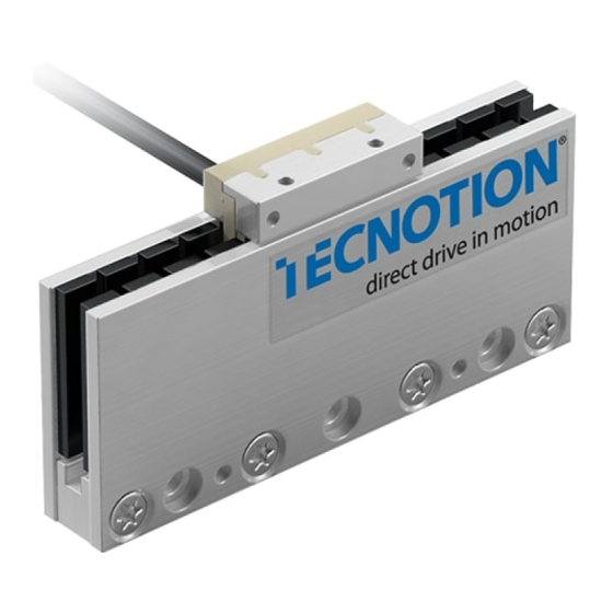
TECNOTION INSTALLING IRONLESS LINEAR MOTORS 2.1. Basic components The basic Linear Motor components supplied by Tecnotion are: • The coil unit (the N and S version differing in voltage and current requirements) Figure 2: Coil unit • The magnet yoke (in different lengths, varying in outer dimensions... -
Page 9: Additional Features
• fixing components, like bolts and pins; • additional devices, like a servo controller and a linear encoder; • the right tools. These features are no part of Tecnotion’s standard delivery. If desired Tecnotion can supply all additional components as well as some types of devices. -
Page 10: Bolts And Dowel Pins
2.2.2. Controller and measurement unit Required is: • An appropriate servo controller/amplifier • A ruler and a linear encoder or an analogue Hall module • Power supply, cabling and connectors For more information please contact Tecnotion. DOCUMENT NR 4022.363.4197.1 COMPONENTS... -
Page 11: Tools
TECNOTION INSTALLING IRONLESS LINEAR MOTORS 2.2.3. Tools Necessary for the installation is: • Allen Key set Occasionally useful are: • Heat sink compound (optional) • Wipes to clean mounting surfaces DOCUMENT NR 4022.363.4197.1 COMPONENTS... -
Page 12: Installation
TECNOTION INSTALLING IRONLESS LINEAR MOTORS Chapter 3. Installation DOCUMENT NR 4022.363.4197.1 INSTALLATION... -
Page 13: Installation Order
TECNOTION INSTALLING IRONLESS LINEAR MOTORS 3.1. Installation order Figure 5: Ironless linear motor system Y oke Coil unit Magnet S lide Mounting surface for magnet track Figure 6: Coil unit, slide, magnet yoke and mounting surface, schematically The installation order of this instruction manual must be followed. -
Page 14: Requirements For The Mounting Surfaces
TECNOTION INSTALLING IRONLESS LINEAR MOTORS 1. Mount the magnet yokes to the mounting surface of the machine. 2. Mount the coil unit to the involved machine parts 3. Connect the wiring to the coil unit. From a magnetical point of view the installation order of the mechanics is not critical, because no attraction is present between the coil unit and magnet yokes. - Page 15 TECNOTION INSTALLING IRONLESS LINEAR MOTORS Specifications: • Surface for coil unit having a flatness better then 0.1mm. • Surface for the track of magnet yokes having a flatness better than 0.1mm. The track of the magnet yokes – from now on to be called the magnet track –...
-
Page 16: Magnet Track Mounting Instructions
(A1 and A2) will be obtained. The dimensions of the coil units and magnet yokes can be found on the internet site of Tecnotion: www.tecnotion.com. 3.3. Magnet track mounting instructions Especially the magnet yokes must be handled with care. - Page 17 TECNOTION INSTALLING IRONLESS LINEAR MOTORS The following yokes can be mounted with mechanical contact using the mutual attraction force of the magnet yokes. Take care: apply the principle of controlled rotational mounting. Uncontrolled approach may cause damage to the magnets (see Figure 9).
-
Page 18: Coil Unit Mounting Instructions
TECNOTION INSTALLING IRONLESS LINEAR MOTORS 3.4. Coil unit mounting instructions Be sure that the mounting surfaces are free of contamination. Particles > 0.1mm can cause inaccurate placement and consequently damage to your Linear Motor. The mounting of the coil unit on appropriate and clean mounting surfaces is very straightforward because no attraction forces are present between coil unit and magnet yokes. -
Page 19: Electrical Connections
TECNOTION INSTALLING IRONLESS LINEAR MOTORS 3.5. Electrical Connections Before starting any activity on the wiring, make sure that the mains are disconnected. Work carefully according the instructions belonging to the applied servo controller. Be sure your machine meets the requirements of the EN 60204 standard. - Page 20 PT C KT Y green Linear motor S lide Figure 10: Wiring scheme UM, UL and UX series ironless S ervo amplifier gr/ye Linear motor S lide Figure 11: Wiring scheme UC series ironless DOCUMENT NR 4022.363.4197.1 INSTALLATION...
-
Page 21: Powerlines
TECNOTION INSTALLING IRONLESS LINEAR MOTORS 3.5.2. Power lines The three phases of the motor’s power cable have to be connected to the servo amplifier in such a way that the positive three phase direction of the motor conforms the positive direction of the linear encoder. This polarization has to be tested, it cannot be seen at first sight. -
Page 22: Temperature Sensor
3.5.4. Temperature Sensor The coil unit of the ironless Linear Motors – except for the UC series – is equipped with two temperature sensors, one of the PTC-1k-type and one of the KTY21-6 type. The PTC resistor is the motor’s standard device for checking the heat production in the coil unit. -
Page 23: Kty Specification
±1ºC if this “thermometer” is calibrated at 1 or 2 relevant temperatures (put the complete coil unit into an oven). Contact Tecnotion if more information is needed. Figure 13: Scheme for obtaining a linear voltage signal from the KTY-sensor DOCUMENT NR 4022.363.4197.1... -
Page 24: Polarization Test
Internally all ironless linear motors are equally wired and connected, so one test satisfies to find out the polarization of a motor ruler combination. If more axes are constructed in a similar way the polarization will be equal. For more information, please contact Tecnotion. DOCUMENT NR 4022.363.4197.1 INSTALLATION... -
Page 25: Operation
TECNOTION INSTALLING IRONLESS LINEAR MOTORS Chapter 4. Operation 4.1. General When you are convinced that your application’s linear motor system is assembled in a proper way, both mechanically and electrically, you can do the next step. You can put your motor system into operation. -
Page 26: Configuring
TECNOTION INSTALLING IRONLESS LINEAR MOTORS 4.2. Configuring The amplifier can be powered up. The following items should be configured as parameter settings of your specific servo amplifier: • Presence and switch mode of end switches, • Presence of an electromechanical brake, •... -
Page 27: Testing
TECNOTION INSTALLING IRONLESS LINEAR MOTORS • Maximum speed (rpm), • Number of increments or periods of feedback device in one rotation (divide pole pitch length by increments per pole pitch). For linear based software: • Pole pitch, • Maximum speed (units!), •... -
Page 28: Starting Up
TECNOTION INSTALLING IRONLESS LINEAR MOTORS 4.4. Starting up Generally spoken, build it up in small steps. Don’t climb the stairs with 2 or 3 steps in one time. Start the tuning with only the speed loop, initially with very low speeds.
Need help?
Do you have a question about the UC Series and is the answer not in the manual?
Questions and answers