Advertisement
Quick Links
INSTRUCTIONS
MODBUS RTU CARD
RIGHT FROM
THE START
Contents
1. Important User Information ................................................................ 2
2. Installation ........................................................................................... 2
3. Operation ............................................................................................. 3
4. Modbus Registers ................................................................................ 4
5. Specifications .................................................................................... 16
Product Compatibility
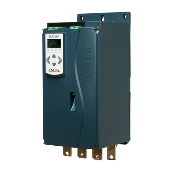
The Modbus RTU Card is suitable for use with EMX4e and EMX4i soft starters.
Disclaimer
The examples and diagrams in this manual are included solely for illustrative
purposes. The information contained in this manual is subject to change at any time
and without prior notice. In no event will responsibility or liability be accepted for
direct, indirect or consequential damages resulting from the use or application of this
equipment.
Warnings
WARNING
For your safety, isolate the soft starter from mains voltage before attaching or
removing accessories.
WARNING
Inserting foreign objects or touching the inside of the starter while the
expansion port cover is open may endanger personnel, and can damage the
starter.
© 2018 AuCom Electronics Ltd. All Rights Reserved.
Modbus RTU Card | Rev B 08/2018
Advertisement

Summary of Contents for AuCom Modbus RTU Card
-
Page 1: Table Of Contents
4. Modbus Registers ................4 5. Specifications ..................16 Product Compatibility The Modbus RTU Card is suitable for use with EMX4e and EMX4i soft starters. Disclaimer The examples and diagrams in this manual are included solely for illustrative purposes. The information contained in this manual is subject to change at any time and without prior notice. -
Page 2: Important User Information
2.2 Connecting to the Network After the card is in place, control power can be restored and field wiring can be connected via the 5-way connector plug. Function 1, 2 Data A Common 4, 5 Data B Modbus RTU Card (710-16499-00B) -
Page 3: Operation
INSTRUCTIONS 3. Operation The Modbus RTU Card must be controlled by a Modbus client (such as a PLC) which complies with the Modbus Protocol Specification. For successful operation, the client must also support all functions and interfaces described in this document. -
Page 4: Modbus Registers
• In Standard Mode, the card uses registers defined in the Modbus Protocol Specification. • In Legacy Mode, the card uses the same registers as AuCom's Modbus Module. Some registers differ from those specified in the Modbus Protocol Specification. The mode of operation is determined by the values of bit 15 in register 40001. - Page 5 INSTRUCTIONS 4.4 Parameter Management Parameters can be read from and written to the starter. The Modbus RTU Card can read or write a maximum of 125 registers in one operation. CAUTION Do not change the default values of the Advanced parameters (parameter group 20).
- Page 6 5 = Not ready (restart delay, restart temperature check, run simulation, reset input is open) 6 = Tripped 7 = Programming mode 8 = Jog forward 9 = Jog reverse 1 = Warning 0 = Unintialised 1 = Initialised Modbus RTU Card (710-16499-00B)
- Page 7 Phase 2 voltage Reserved 14 to 15 30616 Voltage 0 to 13 Phase 3 voltage Reserved 14 to 15 30617 Parameter list 0 to 7 Parameter list minor revision version number 8 to 15 Parameter list major version Modbus RTU Card (710-16499-00B)
- Page 8 Reserved 8 to 15 Reserved 30620~ 30631 NOTE Reading register 30603 (Changed parameter value) will reset registers 30602 (Changed parameter number) and 30604 (Parameters have changed). Always read registers 30602 and 30604 before reading register 30603. Modbus RTU Card (710-16499-00B)
- Page 9 6 = 1) 1 = Current exceeds FLC 0 = Unintialised 1 = Initialised Reserved 7 to 15 Reserved 40004 40005 Motor current 0 to 7 Average 3-phase motor current (A) Reserved 8 to 15 Modbus RTU Card (710-16499-00B)
- Page 10 6 = Tripped 7 = Programming mode 8 = Jog forward 9 = Jog reverse 1 = Warning 0 = Unintialised 1 = Initialised Command source 0 = Remote Keypad, Digital Inputs, Clock 1 = Network Modbus RTU Card (710-16499-00B)
- Page 11 Phase 2 voltage Reserved 14 to 15 40616 Voltage 0 to 13 Phase 3 voltage Reserved 14 to 15 40617 Parameter list 0 to 7 Parameter list minor revision version number 8 to 15 Parameter list major version Modbus RTU Card (710-16499-00B)
- Page 12 Starter Address Function Code Register Data 40004 CRC1, CRC2 00000010 CRC1, CRC2 Download parameter from starter Locked Rotor Current Read Parameter 5 (1E ), 600% Message Starter Address Function Code Register Data 40013 CRC1, CRC2 2 (bytes) CRC1, CRC2 Modbus RTU Card (710-16499-00B)
- Page 13 Instantaneous overcurrent Power loss Undercurrent Heatsink overtemperature Motor connection Input A trip FLC too high Unsupported option (function not available in inside delta) Communications card fault Forced network trip Internal fault Overvoltage Undervoltage Parameter out of range Modbus RTU Card (710-16499-00B)
- Page 14 Motor Connection T3 Firing Fail P1 Firing Fail P2 Firing Fail P3 VZC Fail P1 VZC Fail P2 VZC Fail P3 Low Control Volts 84~96 Internal fault x. Contact your local supplier with the fault code (X). Modbus RTU Card (710-16499-00B)
- Page 15 The adapter or starter does not support one of the received data values Slave device error An error occurred while trying to perform the requested function Slave device busy The adapter is busy (for example writing parameters to the starter) Modbus RTU Card (710-16499-00B)
-
Page 16: Specifications
Data rate (bps) ..............4800, 9600, 19200, 38400 Parity ................None, Odd, Even, 10-bit Timeout ............... None (Off), 10 s, 60 s, 100 s • Certification RCM ....................IEC 60947-4-2 CE ....................EN 60947-4-2 RoHS ............. Compliant with EU Directive 2011/65/EU Modbus RTU Card (710-16499-00B)


Need help?
Do you have a question about the Modbus RTU Card and is the answer not in the manual?
Questions and answers