Bernard Controls SQX Series Instructions For Start-Up
Hide thumbs
Also See for SQX Series:
- Instructions for start-up (28 pages) ,
- Instructions manual (79 pages)
Table of Contents
Advertisement
Advertisement
Table of Contents

Related Manuals for Bernard Controls SQX Series


Summary of Contents for Bernard Controls SQX Series
- Page 1 instructions for start-up sqx & stx intelli+ ranges (CSA certified) Range...
-
Page 2: Table Of Contents
8 Local control using buttons and display Page 12 9 Navigating in the menus Page 12 BERNARD CONTROLS cannot be judged responsible for the non-respect of these rules. 9.1 Selectors Page 12 9.2 Main menu Page 13 Our actuators have been designed for a use in hazardous (Classified) locations: 9.3 Select a menu or an option... -
Page 3: Installation Area
1.2 INSTALLATION AREA 1.3 CAUTIONS FOR ELECTRICAL CONNECTION This actuator is an explosion-proof equipment and can be used in the following areas depending Opening the covers on the marking : To avoid any risk of explosion, do not open when explosive atmosphere may be present. It is prefe- rable that the actuator electric control and power supply are switched off before opening the cover. -
Page 4: Operation
Dimensions of explosion proof joints are specifics. Consult BERNARD CONTROLS for information. 1.6 ELECTRICAL AND TEMPERATURE PARAMETERS Water-proofness Because the NPT cable gland thread is not IP68, it’s necessary to mount it with a thread sealant for ex: Loctite... -
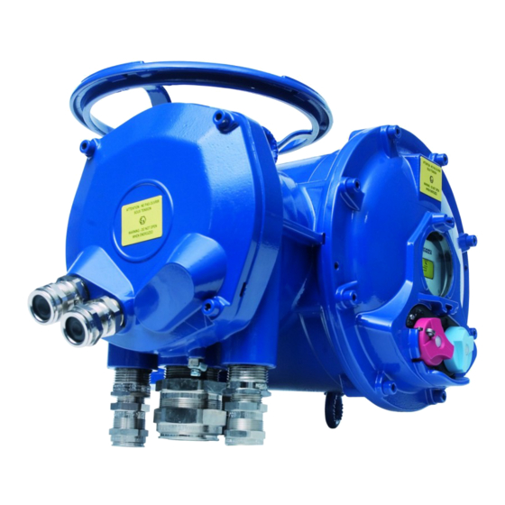
Page 5: Product Overview
2 PRODUCT OVERVIEW 3 STORAGE Introduction Terminal An actuator consists of electrical components plus mechanical parts which have life-long lubrication. compartment Although the assembly is contained in a waterproof housing, the actuators may suffer from oxidation, become clogged or seize during commissioning if it has not been stored correctly. Storage Actuators must be stored under cover in a clean, dry place which is protected against variations in temperature. -
Page 6: Electrical Connection
5 ELECTRICAL CONNECTION 7 REMOTE CONTROL Only the cover of the connection box/compartment (Fig. 2) requires to be open for electrical connec- The INTELLI+ actuator’s remote control system can be operated using an external or an integral tion. The other covers should not be removed at the risk of introducing moisture into the electronic voltage supply. -
Page 7: Local Control Using Buttons And Display
8 LOCAL CONTROL USING BUTTONS AND DISPLAY 9.2 MAIN MENU The local control facility provides a means of operating - Set the selector on local the actuator electrically without using an external control - Keep the red selector on local stop and at the same time move the blue selector upwards and circuit. -
Page 8: Exiting The Menu At Any Times
9.5 ExITING ThE MENU AT ANY TIMES 12 ChECK MENU FLOWChART To exit the menu at any time, turn the red selector to the “OFF” position. MENU RETURN return ACTIVITY EXIT number of starts SETUP running time ALARMS no alarm starts last 12h LANGUAGE return... -
Page 9: Set Up And Change Menu Flowchart
14 ADJUSTING AN ACTUACTOR ON A VALVE 13 SET UP AND ChANGE MENU FLOWChART The SET UP menu is used to set the open and closed positions when the actuator has been on (position) SET UP installed on the valve. Settings can be made manually by choosing MENU RETURN on (torque) -
Page 10: Automatic Set Up
14.2 AUTOMATIC SET UP One of the auxiliary commands has to be set to AUTO / ON-OFF to operate remotely (see §16.3). The actuator is on positioner control when this setting has been completed. The auxiliary command must be switched for On-Off commands. This auxiliary command is used for selecting positioner or Select set up in the MENU and turn to OK to confirm. -
Page 11: Local Commands
- auto/on off: actuators used to control equipment with the AUX. COMMAND 1 AUTO / ON - OFF positioner function can be a DC signal driven (e.g. 4-20 mA) or no assigned Select change in the MENU and turn to OK to confirm. contact (c) = auto via open/close/stop commands. -
Page 12: Open Or Close Priority
Select commands in the CHANGE menu and turn to OK to confirm. Pocket PC : BERNARD CONTROLS can supply a rugged Pocket PC for site use: waterproof or explo- Select priority in the COMMANDS menu and turn to OK to confirm. -
Page 13: Setting And Viewing Torque Values
Bluetooth menu Description of torque limit system: BLUETOOTH To access the Bluetooth menu : All torque values are expressed as percentages. Return 100% corresponds to the maximum setting for the actuator. Select CHANGE in the MENU and OK PIN Code Enter the password and OK This value is shown in Nm on the actuator nameplate. -
Page 14: Customizing Status And Control Indications
If the torque values for a previous motorised movement have been stored in memory, these values 19.2 REMOTE INDICATIONS can be viewed in the next line for reference. Example: in this example, the torque reading on the initial move- Signals giving actuator status data are transmitted via bistable relays. Each relay can be configured CLOSING% ment was 12% and the torque on the most recent movement applying a list of available options. -
Page 15: Customizing Fault Relay
Some of the selections have further options, see next page; 21 TIMING MOVEMENT TRAVEL FROM X% AND Y% return INTELLI+ includes a timing module for reducing the actuator’s operating speed (for example to protect (from x% to y%) a line against pressure surges). Specify contact action range after turning to OK to confirm: The timing system applies a series of on / off commands to the motor when an open or close command return... -
Page 16: Viewing Actuator History
22 VIEWING ACTUATOR hISTORY 23 ACCESSING DATA ShEET To check settings without making To check settings without making changes, select check instead 22.1 ACTIVITY Select change in the MENU and turn to OK to confirm. changes, select check instead of change in the menu. Select data sheet in the CHANGE menu and turn of change in the menu. -
Page 17: Creating Or Changing Password
external gear ratio 1/: indication of gear stepdown ratio for an additional gear. For example, for a quarter-turn gear with a ratio of 1:120, enter 120. OPT POSIT SIGNAL Travel will then be indicated in degrees. To select the signals’ direction of variation and type signal ( ) opening thread in mm: Indication of pitch of a linear system to allow travel to be displayed in mm, rather Select change in the MENU and turn to OK to confirm. -
Page 18: Setting Of Deadband Value
Bus control: Bus control is normally selected. For equipment which also uses a standard hard- 26.2 SETTING OF DEADBAND VALUE wired system, this configuration allows the user to chose the command mode: either via bus or hard-wired (see §7.1 and §7.2) The deadband value is the maximum allowable difference between the signal and the actuator position when no action occurs. -
Page 19: Fuse Protection
29 FUSE PROTECTION 32 TROUBLEShOOTING The INTELLI+ power supply system includes a transformer and a number of fuses. 32.1 INTELLI+ Primary: 6.3x32 mm - 0.5 A - quick-action fuse (located on the transformer). Secondary: Internal circuits protected by automatic cut-out (no user action needed) 24V auxiliary If there is any doubt about the operation of the system, first set the local / remote selector in the power supply on terminal protected by automatic cut-out (no user action needed) local position and then operate the open and close controls. -
Page 20: Positioner Option
32.2 POSITIONER OPTION Below are a few additions applicable to the control version by positioner analog signal. - Page 22 NOTES NOTES...
-
Page 23: Bernard Controls Inc
MOSCOW aquatel@laposte.net mail@bernardcontrols.com BERNARD CONTROLS CHINA Tel +212 22 66 55 71 Tel +33 (0)1 34 07 71 00 RUSSIA BERNARD CONTROLS CHINA youri.otradine@bernardcontrols.com PEKIN POLAND Tel +(7 499) 251 06 54 inquiry.asia@bernardcontrols.com ARNAP Z.o.o. Contact directly agents/distributors or +(7 916) 911 28 42...
Need help?
Do you have a question about the SQX Series and is the answer not in the manual?
Questions and answers