Bernard Controls SQX Series Instructions Manual
Hide thumbs
Also See for SQX Series:
- Instructions for start-up (23 pages) ,
- Instructions for start-up (28 pages)

Related Manuals for Bernard Controls SQX Series


Summary of Contents for Bernard Controls SQX Series
- Page 1 INSTRUCTIONS FOR START-UP SQX & STX INTELLI+ RANGES MANUEL DE MISE EN SERVICE GAMMES SQX & STX INTELLI+ (ATEX & IECEx) Gamme Range...
-
Page 2: Table Of Contents
CONTENTS 1 Safety information Page 3 1.1 Marking Page 3 1.2 Installation Area Page 4 1.3 Cautions for electrical connection Page 4 1.4 Operation Page 6 1.5 Maintenance Page 6 1.6 Electrical and temperature parameters Page 6 1.7 Special operation conditions including unconrrect practices Page 7 1.8 List of applicable standards Page 7... -
Page 3: Safety Information
BERNARD CONTROLS cannot be judged responsible for the non-respect of these rules. Our actuators have been designed for a use in explosive atmospheres: group II - category 2 in presence of vapour, fog or gas (G) or dust (D). -
Page 4: Installation Area
1.2 INSTALLATION AREA This actuator is a category 2 explosion-proof equipment and can be used in the following areas depending on the marking : Actuator type STX.., ST175, ST220 Protection Ex d, Ex de, Ex tb Ex d, Ex tD Ex d , Ex de, Ex tb Category 2 (EPL Gb, Db) - Page 5 Screws of explosion-proof actuator body must be of a minimum 8.8 quality grade or made of stainless steel with a minimum 70 daN/mm2 tensile strength. In case of use in explosive dust atmosphere, check that cover tightness gaskets are intact and make sure not to degrade the gas- kets while closing the cover.
-
Page 6: Operation
Any repair on the explosion proof or the increased safety device requires a prior manufacturer agreement and generally necessitates to return it to the manufacturer workshop in order to secure the explosion proof and increased safety protection integrity. Dimensions of explosion proof joints are specifics. Consult BERNARD CONTROLS for information. Paint coating repair WARNING In case actuator operates in group IIC and painting must to be repaired, make sure that max. -
Page 7: Electrical And Temperature Parameters
1.6 ELECTRICAL AND TEMPERATURE PARAMETERS The power supply voltage and frequency are indicated on the identification tag and (or) on the electric wiring diagram. The minimum ambiant temperature is -20°C and the maximum +40°C unless an other information is mentioned on the identification tag. 1.7 SPECIAL OPERATION CONDITIONS INCLUDING UNCORRECT PRACTICES Duty cycle: the motors are designed for an intermittent operation ;... -
Page 8: Product Overview
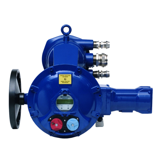
2 PRODUCT OVERVIEW Terminal compartment Emergency handwheel Fieldbus connection Power and hardwired controls connection Remote control box configuration Infrared port display Open & closed valve indication LEDs Blue selector Red selector Open/Close & Local/Distance/Stop Up-Down Scroll & validation (OK) Manual override All INTELLI+ actuators incorporate a handwheel for manual control with an automatic clutch system with motor-drive priority. -
Page 9: Storage
3 STORAGE Introduction An actuator consists of electrical components plus mechanical parts which have life-long lubrication. Although the assembly is contained in a waterproof housing, the actuators may suffer from oxidation, become clogged or seize during commissioning if it has not been stored correctly. Storage Actuators must be stored under cover in a clean, dry place which is protected against variations in temperature. -
Page 10: Electrical Connection
5 ELECTRICAL CONNECTION Only the cover of the connection box/compartment (Fig. 2) requires to be open for electrical connec- tion. The other covers should not be removed at the risk of introducing moisture into the electronic controls. A wiring diagram is normally supplied with the actuator. If this is not the case, please ask our customer service. -
Page 11: Remote Control
7 REMOTE CONTROL The INTELLI+ actuator’s remote control system can be operated using an external or an integral voltage supply. The input circuits are fully opto-isolated. The self-hold pulse command system requires four connec- ting wires on the client terminal strip: Common, stop, open and close. If the stop push-button is not used, do not connect the STOP wire, open (or close) contact must be maintained to operate the actuator. -
Page 12: Local Control Using Buttons And Display
8 LOCAL CONTROL USING BUTTONS AND DISPLAY The local control facility provides a means of operating the actuator electrically without using an external control circuit. There is a switch for selecting remote control, local control or disabled (off). The local open/close switch is used to operate the actuator in the direction required. -
Page 13: Main Menu
9.2 MAIN MENU - Set the selector on local - Keep the red selector on local stop and at the same time move the blue selector upwards and then downwards. The display shows: MENU exit setup - Release the selector, it goes to “local” position. To read the menu, turn the blue selector up or down to scroll through the menu options on the bottom line of the display. -
Page 14: Exiting The Menu At Any Times
9.5 EXITING THE MENU AT ANY TIMES To exit the menu at any time, turn the red selector to the “OFF” position. 9.6 MAIN MENU DESCRIPTION Language: to choose the displayed language. MENU Check: to view all actuator settings and configuration data. exit set up No changes can be made and this option can be accessed language... -
Page 15: Check Menu Flowchart
12 CHECK MENU FLOWCHART MENU RETURN return ACTIVITY EXIT number of starts SETUP running time ALARMS no alarm starts last 12h return LANGUAGE handwheel action aux. command 1 COMMANDS aux. command 2 CHECK local command local stop SET UP remote stop priority CHANGE fault tolerance... -
Page 16: Set Up And Change Menu Flowchart
13 SET UP AND CHANGE MENU FLOWCHART on (position) MENU RETURN on (torque) on (torque) O/C CLOSING MODE EXIT (CW) SET UP CLOSE (CCW) DIRECTION (change ok?) user return code LANGUAGE (no change) POSITION valve closed? SETTING valve open? RETURN automatic CHECK return... -
Page 17: Adjusting An Actuactor On A Valve
14 ADJUSTING AN ACTUACTOR ON A VALVE The SET UP menu is used to set the open and closed positions when the actuator has been SET UP installed on the valve. Settings can be made manually by choosing return the open and closed positions, or automatically. In automatic closing mode mode, the actuator rotates and halts at the end positions in response closing direction... -
Page 18: Automatic Set Up
14.2 AUTOMATIC SET UP Select set up in the MENU and turn to OK to confirm. Warning: during automatic Select closing mode in the SET UP menu and turn to OK setting the actuator halts on to confirm. Select whether valve to close on basis of torque mechanical stops so take care or position both open and close actions can be set on torque). -
Page 19: Commands
One of the auxiliary commands has to be set to AUTO / ON-OFF to operate remotely (see §16.3). The actuator is on positioner control when this setting has been completed. The auxiliary command must be switched for On-Off commands. This auxiliary command is used for selecting positioner or on-off control remotely. - Page 20 AUX. COMMAND 1 no assigned Select change in the MENU and turn to OK to confirm. local/remote Select commands in the CHANGE menu and turn to OK to confirm. local+remote/remote Select aux. command 1 or aux. command 2 local command inhibit in the COMMANDS menu and turn to OK to confirm.
-
Page 21: Local Commands
- auto/on off: actuators used to control equipment with the AUTO / ON - OFF positioner function can be a DC signal driven (e.g. 4-20 mA) or contact (c) = auto via open/close/stop commands. The auto/ on-off command contact (o) = auto provides a means of switching over from one command mode to the other. -
Page 22: Open Or Close Priority
90 - 160V* ~ 10 - 55V ~ STOP STOP CLOSE CLOSE OPEN OPEN *160 to 250V in option 16.6 OPEN OR CLOSE PRIORITY There are no priorities on open or close in the standard configuration. Priorities are used to reverse the direction of travel when an action is in progress without having to give a stop command. -
Page 23: Infrared Communication
(See the software handbook for further details). Pocket PC : BERNARD CONTROLS can supply a rugged Pocket PC for site use: waterproof or explo- sion-proof versions are available. The device is supplied with the software pre-installed. -
Page 24: Setting And Viewing Torque Values
Bluetooth menu BLUETOOTH To access the Bluetooth menu : Return Select CHANGE in the MENU and OK PIN Code Enter the password and OK On/Off Select BLUETOOTH and OK. Return The PIN code can be modified. This code will be requested when attempting to connect to the actuator. -
Page 25: Torque Reading And Comparison With Original Torque Values
Description of torque limit system: All torque values are expressed as percentages. 100% corresponds to the maximum setting for the actuator. This value is shown in Nm on the actuator nameplate. - closing % : limits torque during closing - close tight %: this option is only displayed if closing is on torque limit. In this case, the torque applied on the valve seat may be not be the same as Note: Actuator settings must be made the torque limit during the closing movement. -
Page 26: Customizing Status And Control Indications
If the torque values for a previous motorised movement have been stored in memory, these values can be viewed in the next line for reference. Example: in this example, the torque reading on the initial move- CLOSING% ment was 12% and the torque on the most recent movement is 18%. -
Page 27: Remote Indications
19.2 REMOTE INDICATIONS Signals giving actuator status data are transmitted via bistable relays. Each relay can be configured applying a list of available options. INTELLI+ has four bistable relays in the standard configuration. A further three bistable relays can be added as an option (the contact is open when there is no power). The equipment is configured at the factory in accordance with the order. -
Page 28: Customizing Fault Relay
Some of the selections have further options, see next page; FROM X% AND Y% return (from x% to y%) Specify contact action range after turning to OK to confirm: return Select x% and turn to OK to confirm. Use the blue selector to increase or decrease the value. Select y% and turn to OK to confirm. -
Page 29: Timing Movement Travel
21 TIMING MOVEMENT TRAVEL INTELLI+ includes a timing module for reducing the actuator’s operating speed (for example to protect a line against pressure surges). The timing system applies a series of on / off commands to the motor when an open or close command is transmitted. -
Page 30: Viewing Actuator History
22 VIEWING ACTUATOR HISTORY To check settings without making 22.1 ACTIVITY changes, select check instead of change in the menu. Select change in the MENU and turn to OK to confirm. Select activity in the CHANGE menu and turn to OK to confirm. - Page 31 23 ACCESSING DATA SHEET To check settings without making changes, select check instead Select change in the MENU and turn to OK to confirm. of change in the menu. Select data sheet in the CHANGE menu and turn to OK to confirm. DATA SHEET valve tag number return...
-
Page 32: Creating Or Changing Password
external gear ratio 1/: indication of gear stepdown ratio for an additional gear. For example, for a quarter-turn gear with a ratio of 1:120, enter 120. Travel will then be indicated in degrees. thread in mm: Indication of pitch of a linear system to allow travel to be displayed in mm, rather than in number of revolutions stroke: Indication of stroke value measured when adjusting valve. -
Page 33: Use As A Positioner With An Analogue Control Signal (Depending On Model)
OPT POSIT SIGNAL To select the signals’ direction of variation and type signal ( ) opening Select change in the MENU and turn to OK to confirm. signal ( ) opening Select position in the CHANGE menu and turn to OK to confirm. Select opt. -
Page 34: Setting Of Deadband Value
26.2 SETTING OF DEADBAND VALUE The deadband value is the maximum allowable difference between the signal and the actuator position when no action occurs. This setting is made at the factory, but it is possible to adjust it. If the deadband is too narrow, the actuator could start hunting, i.e opening and closing around the expected position without being able to stabilise. -
Page 35: Using In Case Of Power Supply Lost (With Battery Depending On Model)
Bus control: Bus control is normally selected. For equipment which also uses a standard hard- wired system, this configuration allows the user to chose the command mode: either via bus or hard-wired (see §7.1 and §7.2) Slave no. Actuator address. All actuators have to have different addresses. The default address is 2. -
Page 36: Fuse Protection
29 FUSE PROTECTION The INTELLI+ power supply system includes a transformer and a number of fuses. Primary: 6.3x32 mm - 0.5 A - quick-action fuse (located on the transformer). Secondary: Internal circuits protected by automatic cut-out (no user action needed) 24V auxiliary power supply on terminal protected by automatic cut-out (no user action needed) 30 USING IN SEPARATED BOX INTELLI+ can be provided in separated box to be removed from the actuato up to 50 meters. -
Page 37: Troubleshooting
32 TROUBLESHOOTING 32.1 INTELLI+ If there is any doubt about the operation of the system, first set the local / remote selector in the local position and then operate the open and close controls. -
Page 39: Positioner Option
32.2 POSITIONER OPTION Below are a few additions applicable to the control version by positioner analog signal. - Page 41 SOMMAIRE 1 Instructions pour la sécurité Page 43 1.1 Marquage Page 43 1.2 Zone d’utilisation Page 44 1.3 Précautions pour le raccordement électrique Page 44 1.4 Utilisation Page 46 1.5 Maintenance Page 46 1.6 Paramètres électriques et températures Page 46 1.7 Conditions particulières d’utilisation y compris d’un mauvais usage Page 47 1.8 Liste des normes appliquées...
-
Page 42: Marquage
1.1 MARQUAGE ATEX protection IECEx protection IEx protection antidéflagrante « d » antidéflagrante « d » antidéflagrante « d » BERNARD CONTROLS BERNARD CONTROLS BERNARD CONTROLS Nom et adresse 4 rue d’Arsonval 95505 4 rue d’Arsonval 95505 4 rue d’Arsonval 95505... -
Page 43: Zone D'utilisation
1.2 ZONE D’UTILISATION Ce matériel antidéflagrant est de catégorie 2 et peut être utilisé dans les zones suivantes : Type de servomoteur STX.., ST175, ST220 Protection Ex d, Ex de, Ex tb Ex d, Ex tD Ex d , Ex de, Ex tb Catégorie 2 (EPL Gb, Db) 2 (EPL Gb, Db) - Page 44 La visserie des enveloppes antidéflagrantes doit être de qualité minimum 8.8 ou en inox de résistance à la rupture de 70 daN/mm² mini. Pour l’utilisation dans les atmosphères poussiéreuses, vérifier le bon état des joints d’étanchéité des cou- vercles et veiller à ne pas détériorer les joints lors de la fermeture. Les entrées de câble devront avoir un degré...
-
Page 45: Utilisation
La dimension des joints antidéflagrants étant spécifique au matériel consulter BERNARD CONTROLS pour information. Réparation de la couche de peinture ATTENTION Si le servomoteur fonctionne en groupe IIC et si la peinture doit être réparée,... -
Page 46: Paramètres Électriques Et Températures
1.6 PARAMETRES ELECTRIQUES ET TEMPERATURES La tension et la fréquence d’alimentation sont indiqués sur la plaque signalétique et (ou) sur le schéma électrique. La température ambiante mini est de -20°C et maxi de +40°C sauf indication contraire sur la plaque signalétique. 1.7 CONDITIONS PARTICULIERES D’UTILISATION Y COMPRIS D’UN MAUVAIS USAGE Service de fonctionnement: Les moteurs sont prévus en service intermittent, c’est-à-dire qu’ils doivent... -
Page 47: Présentation
2 PRÉSENTATION Raccordement élec- trique / bus de terrain Volant de commande manuelle Connexion bus Connexion électrique de terrain et câblage standard Version boîtier séparé Liaison infrarouge affichage Voyants vanne ouverte et fermée Bouton bleu ouverture, Bouton rouge fermeture et flèches pour local/distance/stop se déplacer dans le menu et validation OK du menu... -
Page 48: Stockage
3 STOCKAGE Introduction Un servomoteur est composé d’éléments électriques et d’une partie mécanique lubrifiée à la graisse. Malgré l’étanchéité de l’enveloppe de cet ensemble, les risques d’oxydation, de gommage et de grippage peuvent apparaître lors de la mise en service du servomoteur si son stockage n’a pas été correctement réalisé. -
Page 49: Montage Sur Vanne
4 MONTAGE SUR VANNE Le servomoteur doit être boulonné sur l’appareil à motoriser. Les servomoteurs BERNARD sont graissés à vie et peuvent fonctionner dans n’importe quelle position. Cependant, les presse-étoupes ne devraient par être orientés vers le haut (étanchéité) et le moteur pas placé en position basse (condensation d’eau interne potentielle). Note 1: ne pas transporter les servomoteurs par le volant sous peine d’endommager le couple roue et vis. -
Page 50: Commande A Distance
La lecture des chapitres suivants permet d’acquérir les connaissances nécessaires au réglage du servomoteur sur vanne : §9. COMMENT NAVIGUER DANS LES MENUS §10. SELECTIONNER LA LANGUE D’AFFICHAGE §18. COMMENT REGLER ET LIRE LES COUPLES (en cas de fermeture sur couple) §18.1 Type de fermeture §18.2 Réglage du couple §14. -
Page 51: Commande Locale Par Boutons
8 COMMANDE LOCALE PAR BOUTONS Une commande locale par boutons est disponible sur le servomoteur. Le bouton rouge permet de choisir la commande distance (remote), local, ou condamné (off). Le bouton de commande locale (bleu) ouverture et fermeture permet de manoeuvrer le servomoteur dans le sens désiré. Le stop local s’effectue par une rotation momentanée du bouton rouge local/ distance. -
Page 52: Accéder Au Menu Principal
9.2 ACCÉDER AU MENU PRINCIPAL - Mettre le bouton rouge sur local - Tourner et maintenir le bouton rouge sur stop local et en même temps tourner le bouton bleu vers le haut puis vers le bas. Le menu principal s’affiche : MENU retour commande - Relâcher le bouton rouge, il se place devant “local”. -
Page 53: Quitter Le Menu À Tout Moment
9.5 QUITTER LE MENU À TOUT MOMENT Il est possible de quitter le menu à tout moment en plaçant le bouton rouge sur la position OFF. 9.6 DESCRIPTION DU MENU PRINCIPAL language : permet de choisir la langue d’affichage. MENU consulter : permet de lire tous les paramètres et la configuration retour commande du servomoteur. -
Page 54: Organigramme Du Menu Consulter
12 ORGANIGRAMME DU MENU CONSULTER MENU RETOUR retour ACTIVITE RETOUR nbre démarrages COMMANDE temps de marche pas d'alarme ALARME démarrages/12h retour LANGAGE action volant commande aux.1 COMMANDES commande aux.2 CONSULTER commande locale stop local REGLER stop distance priorité MODIFIER mode dégradé ESD course partielle RETOUR retour... -
Page 55: Organigramme Du Menu Régler Et Modifier
13 ORGANIGRAMME DU MENU REGLER ET MODIFIER on (position) MENU RETURN on (torque) on (torque) O/C CLOSING MODE EXIT (CW) SET UP CLOSE (CCW) DIRECTION (change ok?) user return code LANGUAGE (no change) POSITION valve closed? SETTING valve open? RETURN automatic CHECK return... -
Page 56: Comment Régler Un Servomoteur Sur Une Vanne
14 COMMENT REGLER UN SERVOMOTEUR SUR UNE VANNE Le menu REGLER permet de régler les positions ouverte et fermée une fois le servomoteur installé sur la vanne. Le réglage peut REGLER être fait manuellement en choisissant les positions ouverte retour et fermée ou automatiquement. -
Page 57: Réglage Automatique
14.2 RÉGLAGE AUTOMATIQUE Attention au réglage automa- tique suivant le type de vanne : Sélectionner régler dans le MENU et confirmer. pendant le réglage automatique le Sélectionner type de fermeture dans le menu REGLER servomoteur s’arrête sur les butées et confirmer. mécaniques. -
Page 58: Commandes
Pour commander à distance, il faut configurer une des commandes auxiliaires en AUTO / ON OFF (voir §16.3). Une fois cette configuration faite le servomoteur est en commande positionneur. Pour faire une commande Tout Ou Rien il faut établir le contact de la commande auxiliaire. Cette commande auxiliaire permet de sélectionner à... - Page 59 Sélectionner modifier dans le MENU et confirmer par ok. COMMANDE AUX. 1 Sélectionner commandes dans le menu MODIFIER et confirmer non affectée par ok. local/distance Sélectionner commande aux.1 ou commande aux. 2 dans le local+distance / distance menu COMMANDES et confirmer par ok. interdiction de cde locale Sélectionner une commande avec le bouton bleu.
-
Page 60: Commande Locale
- auto/on off : Pour un servomoteur utilisé en régulation avec la fonction positionneur, il est possible de faire des commandes à distance par un signal continu (ex : 4- 20 mA) ou par des commandes ouverture/ fermeture/stop. La commande auto/ on off permet de basculer d’un type de commande à... -
Page 61: Stop Distance
16.5 STOP DISTANCE En standard le stop distance se fait par ouverture d’un contact (alors que la commande ouverture ou fermeture se fait par fermeture d’un contact). Pour commander le stop distance comme l’ouverture ou la fermeture, sélectionner stop distance dans le menu COMMANDES puis choisir contact (f)=stop. -
Page 62: Course Partielle
Pocket PC : Nous consulter pour connaître la compatibilité de communication en fonction du modèle. BERNARD CONTROLS peut aussi fournir un Pocket PC robuste pour utilisation sur site en version étanche ou antidéflagrante. Ce Pocket PC est livré avec le logiciel installé. -
Page 63: Comment Régler Et Lire Les Couples
19.2 COMMUNICATION PAR BLUETOOTH (SUIVANT EQUIPEMENT) A partir de la version 3.01 d’INTELLISOFT / INTELLIPOCKET et seulement si l’option Bluetooth a été installée sur le contrôle INTELLI+, il est possible de communiquer sans câble et jusqu’à une distance de 10 mètres. Remarques : Pour une connexion avec un PC, utiliser une clef Bluetooth, classe II - Version 2.1 + EDR (Mini- mum). -
Page 64: Lire Les Couples Mesurés Et Les Comparer Aux Couples D'origine
Sélectionner le réglage voulu et confirmer par OK. Incrémentez ou décrémenter la valeur avec le bouton bleu. FERMETURE % Le réglage mini est de 40%. (100) En maintenant le bouton, le défilement des chiffres s’accélère. Description des limitations de couple Tous les couples sont donnés en pourcentage. -
Page 65: Comment Personnaliser Les Signalisations
Mémoriser les couples d’une manoeuvre électrique Pour mémoriser les couples d’une manoeuvre électrique sélectionner dans le menu mémoriser puis choisir : couple => ref (oui). Les couples notés réf. prennent alors la valeur des couples de la dernière manoeuvre électrique. En cas d’erreur sélectionner de nouveau couple =>... -
Page 66: Signalisation Distance
19.2 SIGNALISATION DISTANCE Les signalisations sont transmises par des relais bistables permettant de connaître l’état du servomoteur. Chaque relais est configurable en fonction d’une liste d’options disponibles. En standard l’INTELLI+ est équipé de 4 relais bistables. Sur demande 3 autres relais monostables (le contact est ouvert hors tension) peuvent être ajoutés. -
Page 67: Comment Personnaliser Le Relais Defaut
Certaines sélections ont des choix complémentaires: ENTRE X% et Y% retour (entre x% et y%) Après confirmation par OK choisir la zone d’action du contact: Sélectionner x% et confirmer par OK. retour Incrémentez ou décrémenter la valeur avec le bouton bleu. Sélectionner y% et confirmer par OK. -
Page 68: Comment Temporiser En Cours De Manoeuvre
21 COMMENT TEMPORISER EN COURS DE MANOEUVRE L’INTELLI+ contient un module temporisateur qui permet de réduire la vitesse de fonctionnement du servomoteur, par exemple pour protéger une canalisation contre les coups de bélier. Quand une commande ouverture ou fermeture est envoyée, une temporisation effectue une commande cadencée marche / arrêt du moteur. -
Page 69: Comment Voir L'activité Du Servomoteur
22 COMMENT VOIR L’ A CTIVITE DU SERVOMOTEUR Pour consulter sans modification, 22.1 ACTIVITÉ sélectionner dans le menu consulter au lieu de modifier. Sélectionner modifier dans le MENU et confirmer par OK Sélectionner activité dans le menu MODIFIER et confirmer par OK. ACTIVITE retour Sélectionner nombre de démarrages ou temps de marche pour... -
Page 70: Comment Accéder A La Fiche Technique
23 COMMENT ACCEDER A LA FICHE TECHNIQUE Sélectionner modifier dans le MENU et confirmer par OK. Pour consulter sans modification, Sélectionner fiche technique dans le menu MODIFIER sélectionner dans le menu consulter et confirmer par OK. au lieu de modifier. FICHE TECHNIQUE retour repère vanne... -
Page 71: Comment Créer Ou Modifier Le Mot De Passe
Détails du menu caractéristiques moteur : cette donnée précise si le moteur est triphasé, mono ou courant continu, (donnée constructeur). protection : version étanche ou antidéflagrante. La sélection antidéflagrante interdit de shunter la protection thermique dans le menu commandes/mode dégradé. blocage moteur en secondes : indication du temps moteur bloqué... -
Page 72: Utilisation En Positionneur A Partir D'un Signal De Commande Analogique (Suivant Équipement)
Les signaux disponibles sont : 4 - 20 mA, 0 - 20 mA, 4 - 12mA ou 12 - 20 mA. Les sorties 4 - 20 mA, 4 - 12mA ou 12 - 20 mA peuvent être raccordées en 2 fils, l’alimentation externe étant en série avec la lecture du signal. -
Page 73: Réglage De La Bande Morte
Signal de commande TYPE DE SIGNAL 4 - 20 mA, 0 - 20 mA, 4 - 12mA ,12 - 20 mA ou 0 - 10 V signal ( ) en ouverture Pour choisir le sens de variation du signal et le type : signal ( ) en ouverture Sélectionner modifier dans le MENU et confirmer par OK. -
Page 74: Utilisation Du Controle Par Bus De Terrain (Suivant Équipement)
27 UTILISATION DU CONTROLE PAR BUS DE TERRAIN (SUIVANT EQUIPEMENT) L’interface bus de terrain permet de commander et transmettre toutes les informations à travers une ligne unique. Une documentation spécifique précise le moyen d’adresser chaque servomoteur et donne une liste d’adresses permettant d’accéder à chaque commande ou information. Le type d’interface bus apparait dans le menu. -
Page 75: Protection Fusibles
29 PROTECTION FUSIBLES L’alimentation de l’INTELLI+ comprend un transformateur et des fusibles. Primaire : fusible 6,3 x 32mm - 0,5A - rapide (situé sur le transformateur). Secondaire : circuits internes, protection par fusible automatique (sans intervention) Alimentation auxiliaire 24V disponible au bornier, protection par fusible automatique (sans intervention). 30 UTILISATION EN COFFRET SEPARE L’INTELLI+ peut être fourni en coffret séparé... -
Page 76: Anomalie De Fonctionnement
32 ANOMALIE DE FONCTIONNEMENT 32.1 INTELLI+ Si le fonctionnement de l’appareil semble douteux, placer en premier lieu le sélecteur local / distance sur la position locale, et agir sur les commandes ouverture et fermeture.. -
Page 78: Option Positionneur
32.2 OPTION POSITIONNEUR Ci-dessous quelques compléments avec la version commande par signal analogique positionneur. - Page 79 BC GROUP Exhaustive list of agents and BELGIUM RUSSIA distributors on BERNARD CONTROLS BENELUX BERNARD CONTROLS RUSSIA BRUXELLES MOSCOW www.bernardcontrols.com inquiry.belgium@bernardcontrols.com inquiry.russia@bernardcontrols.com inquiry.holland@bernardcontrols.com Tel. +7 343 222 06 01 Tel. +32 (0)2 343 41 22 SINGAPORE BERNARD CONTROLS SINGAPORE CHINA...
Need help?
Do you have a question about the SQX Series and is the answer not in the manual?
Questions and answers