Table of Contents
Advertisement
Quick Links
Advertisement
Table of Contents

Related Manuals for Bernard Controls AT SWITCH RANGE


Summary of Contents for Bernard Controls AT SWITCH RANGE
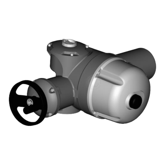
- Page 1 AT SWITCH RANGE Start Up Guide SUG_17010_EN - Ind. D Art : 5100830...
-
Page 3: Table Of Contents
TABLE OF CONTENTS SAFETY ---------------------------------------------------------- 5 PACKAGING, STORAGE AND MAINTENANCE ----------------- 5 Packaging Storage Maintenance ASSEMBLY ------------------------------------------------------- 6 For actuators with a cam block spring (class III) EMERGENCY MANUAL COMMAND ----------------------------- 7 ELECTRICAL COMMISSIONING --------------------------------- 8 Opening/Closing electrical compartment Wiring Calibration of travel limits Calibration of position indicator (OPTION) Calibration of position feedback (OPTION) - Page 4 English...
-
Page 5: Safety
English 1 SAFETY This device complies with current applicable safety standards. The installation, maintenance, and use of this unit require a skilled and trained staff. Please carefully read this entire document before mounting and starting up the actuator. 2 PACKAGING, STORAGE AND MAINTENANCE 2.1 Packaging The packaging of AT SWITCH actuators is comprised of a dual-layer cardboard box strapped on a pallet. -
Page 6: Maintenance
English What to check on pre-installed actuators If you expect a long delay between actuator valve mounting and electrical wiring, visually check that the cable entries and cover are tightly closed. 2.3 Maintenance All AT SWITCH actuators feature lifetime lubrication and therefore require no specific maintenance, under the condition that they were correctly commissioned and used in the conditions they were designed for. -
Page 7: For Actuators With A Cam Block Spring (Class Iii)
English 3.1 For actuators with a cam block spring (class III) The spring (1) is located under the cam block. Both positions and number of turns have been calibrated in factory according to customer request. Before mounting the actuator on the valve, manually or electrically put the actuator in the same position as the valve: either both open on both closed... -
Page 8: Electrical Commissioning
English 5 ELECTRICAL COMMISSIONING 5.1 Opening/Closing electrical compartment You need to open the electrical compartment to wire the actuator. Position indicator option If the closing direction is not standard (clockwise), please configure the position indicator accordingly (see § 5.4) if this operation has not already been performed. -
Page 9: Wiring
English 5.2 Wiring Components (with cover open) 9 – Cable entry plugs 8 – Heating resistance 7 – External ground terminal 6 – Internal ground terminal 5 – Terminal blocks 4 – Torque limiter 3 – Capacitor (only for single phase actuators) 2 –... - Page 10 English Wiring • Internal wiring To perform the wiring, remove the cover and pass the cables through the cable glands, then connect the wires on the terminal blocks. Please refer to the supplied wiring diagram for terminal numbering. Both the heating resistance (9) and torque limiter (5) switches must be integrated into your control system to prevent potential damage to the actuator or valve.
-
Page 11: Calibration Of Travel Limits
English 5.3 Calibration of travel limits Cam-block detail To stop the movement at end positions, the AT SWITCH actuator features a set of cams integrated as a cam block. Cams trip switches to switch off the power at end positions, or for signaling. The cam block is made up of 4 cams. - Page 12 English How to calibrate the cams In the case of actuators with a cam block spring (class III), make sure that the actuator has been prepared according to § 3.1. Make sure that the cam operates the lever in the right direction; otherwise the switch could be damaged.
-
Page 13: Calibration Of Position Indicator (Option)
English 5.4 Calibration of position indicator (OPTION) Handling position indication The position indicator (A) can indicate travels from 90° to 300°. The angle is indicated by 2 markers held by 2 rotating rings: • (2a): red marker tagged “C” (for CLOSED). •... - Page 14 English Calibration of the indicator To calibrate position indicator 1. Open the indicator. 2. Operate the actuator electrically towards the CLOSED position until it stops on the end position switch. 3. Set the position of the position indicator if necessary. 4.
- Page 15 English Changing closing direction indication if necessary As a standard, AT SWITCH actuators are configured to close clockwise. If the actuator must close counterclockwise, you can modify the opening and closing orientations of the position indicator. To change closing direction indication 1.
-
Page 16: Calibration Of Position Feedback (Option)
English 5.5 Calibration of position feedback (OPTION) Position feedback board Two components can be used for position feedback: • a potentiometer (1). • a “TAM” (2), which gives position feedback from a 4-20 mA signal. The potentiometer can be used alone (Positioner) or can be combined with... - Page 17 English Signal direction inversion If the TAM transmitter is fitted on an actuator which closes counterclockwise direction, it provides a signal that increases from the closed position to the open position. If an opposite signal variation is required, simply move 2 jumpers (1) on the board near the potentiometer: •...
-
Page 18: Calibration Of Positioner (Option)
English 8. Turn the screw marked “20 mA” so that it reads 20 mA on the milliammeter. 9. Come back to the closed position and check that for the 0% position, the signal current shows a value close to 0/4 mA and repeatable. -
Page 19: Heating Resistance
English 5.7 Heating resistance Each actuator includes a heating resistance. As soon as the actuator is installed in the field, it is required to supply the resistance to prevent condensation. • Immediately put the cover back in place after start-up while ensuring its seal is clean. -
Page 20: Torque Limiting Device
English 6 TORQUE LIMITING DEVICE 6.1 Torque limiter operation The actuator is protected by a torque limiting device in case of over- torque. 4 – Closing direction torque scale 3 – Opening direction torque scale 2 – Counterclockwise direction cam 1 –... -
Page 21: Torque Limiter Calibration
English 6.2 Torque limiter calibration The torque scale sectors are factory-set and are a reference for cam calibration. Do not modify their position or you will not be able to accurately adjust the torque limiter anymore. Actuators are calibrated and tested in factory according to the torque stated on orders. - Page 22 English NOTES...
- Page 24 Tel.: +33 (0)1 34 7 71 00 / Fax: +33 (0)1 34 07 71 01 / mail@bernardcontrols.com CONTACT BY OPERATING AREAS > AMERICA > EUROPE > INDIA, MIDDLE EAST & AFRICA NORTH AMERICA BELGIUM AFRICA BERNARD CONTROLS UNITED STATES BERNARD CONTROLS BENELUX BERNARD CONTROLS AFRICA HOUSTON NIVELLES (BRUSSELS) ABIDJAN - IVORY COAST inquiry.usa@bernardcontrols.com inquiry.belgium@bernardcontrols.com inquiry.africa@bernardcontrols.com...
Need help?
Do you have a question about the AT SWITCH RANGE and is the answer not in the manual?
Questions and answers
Problem in operation and making commesion
The manual provides information on the commissioning and operation of the AT SWITCH RANGE but does not explicitly list common operational issues or commissioning problems. However, potential issues may include:
1. Electrical Compartment Access – Difficulty in opening/closing the compartment for wiring.
2. Wiring Errors – Incorrect wiring connections may lead to malfunction.
3. Calibration Issues – Errors in calibrating travel limits, position indicators, position feedback, or the positioner.
4. Torque Limiting Device Malfunction – Incorrect torque limiter calibration may cause improper actuator operation.
5. Heating Resistance Issues – Failure to properly configure heating resistance may affect performance in certain environments.
Proper installation, wiring, and calibration by trained personnel can help prevent these issues.
This answer is automatically generated