
Related Manuals for Bernard Controls FSE Series


Summary of Contents for Bernard Controls FSE Series
- Page 1 avrora-arm.ru +7 (495) 956-62-18 RANGE SUG_19002_EN - Ind. A Start Up Guide Art : 5100705...
-
Page 2: Table Of Contents
English TABLE OF CONTENTS Definitions --------------------------------------------------------------------- 5 Introduction ------------------------------------------------------------- 6 Safety information Specifications of the actuator Identifying Actuator Parts Installation and mounting information Service information Identification of FSE actuator OPERATION ------------------------------------------------------------ 20 Modulation and configuration of FSE for ON/OFF application 23 Home Screen Basic Setup Advance Setup... - Page 3 English Maintenance and Troubleshooting --------------------------------- 72 General maintenance Replacement of the filter Replacement of the hydraulic fluid...
-
Page 4: Definitions
English Definitions NOTE: Advisory information comments provided assist maintenance personnel to carry out maintenance procedures. WARNING If not observed, user incurs a high risk of severe damage to product and/or fatal injury to personnel. CAUTION If not observed, user may incur damage to product and/or injury to personnel. -
Page 5: Introduction
English Introduction Thank you for choosing BERNARD CONTROLS product. FSE range Actuators are self-contained; electro-hydraulic actuators which are particularly well suited for applications requiring critical control and high reliability. There are two major components to the FSE range: the actuator which mounts onto the driven device (a valve), consists of the cylinder (in case of double acting) or cylinder with spring module (in case of single acting) ;... - Page 6 Manufacturer Warranty For the safety, it is vital to follow instructions in the manual. It is not BERNARD CONTROLS’s liability for any damages which caused by users' negligence. It is not BERNARD CONTROLS's liability for any damages or accidents which resulted by any alteration or modification of the product and parts.
-
Page 7: Safety Information
Safety information READ THESE INSTRUCTIONS CAREFULLY BEFORE INSTALLING AND USING THE PRODUCT Products supplied by BERNARD CONTROLS, in its "as shipped" condition, are intrinsically safe if the instructions contained within this Service Instruction are strictly adhered to and executed by well- trained, equipped, prepared and competent personnel. - Page 8 English Marking ATEX IECEx Explosionproof Explosionproof enclosure “d” enclosure “d” Name and BERNARD CONTROLS address of the 4 rue d’Arsonval - 95505 Gonesse France manufacturer Actuator type Serial number Serial n°YYAXXXXX.ZZZ Serial n° n°YYAXXXXX.ZZZ Certificate Pending Pending number Specific marking N°...
- Page 9 English Start-up WARNING – DO NOT OPEN WHEN AN EXPLOSIVE ATMOSPHERE IS PRESENT To avoid any risk of explosion, the actuator electric control and power supply must be switched off before opening the cover. Be careful not to damage the joint surfaces of the cover either at the opening and closing of the cover, when ...
- Page 10 English Waterproofness Because the NPT cable gland thread is not IP68, it’s necessary to mount it with a thread sealant for ex: Loctite 577 (Henkel). In case of ISO thread, sealing is assured by an O-ring or by a thread sealant as noticed above.
- Page 11 English Installation area This actuator is an explosion-proof equipment and can be used in the following areas: Protection Category Division Atmosphere class Ex db, Ex tb 2 (EPL Gb/Db) Zone 1 or 2 G Gas / D Dust EPL (Equipment Protection Level): b=high level Gas (G) and Dust (D). Zone 1 (gas) &...
-
Page 12: Specifications Of The Actuator
English Special operation conditions including incorrect practices Covers opening Removing the covers is authorized only when the actuator power supply is switched off and no explosive atmosphere is present. It is important not to degrade the explosion-proof protections (surfaces, cable entries, joints ...). Use the notches or bosses in order to keep seals and cover integrity. -
Page 13: Identifying Actuator Parts
English Identifying Actuator Parts... -
Page 14: Installation And Mounting Information
English Installation and mounting information WARNING For the protection of personnel working on BERNARD CONTROLS actuators, this procedure should be reviewed and implemented for safe installation, disassembly and reassembly. Close attention should be noted to the WARNINGS, CAUTIONS and NOTES contained in this procedure. - Page 15 English If it is necessary to lift the FSE assembly, then use certified slings to lift the FSE assembly with the help of lifting eyebolts as shown in the figure. WARNING Use the lifting eye bolts for lifting the FSE assembly only. ...
-
Page 16: Service Information
Attention should be directed to threads, sealing surfaces and areas that will subjected to sliding and rotating motion. BERNARD CONTROLS recommends that disassembly of the actuator modules should be done in a clean area on a workbench. - Page 17 English WARNING Compressed Springs All springs within the FSE range of actuators are pre-compressed. Springs must not be removed from the actuator. WARNING Hydraulic Fluid FSE actuators are filled with hydraulic fluid Should there be a requirement to change the fluid, then first ensure that the system is depressurized, and the appropriate protective clothing including gloves and safety glasses are worn.
-
Page 18: Identification Of Fse Actuator
English Identification of FSE actuator... -
Page 19: Operation
English OPERATION Operation by the local and remote selector switch Local/Remote Selection: Local/Remote selection is via two rotary switches located on the control module. Rotate fully anti-clockwise is the remote control position. Rotate fully clockwise is the local control position. The mid position is offline, prohibiting the local or remote control of the actuator. - Page 20 English Open/Close Selection: Open/Close selection is via another rotary switch located on the control module. Rotate fully anti- clockwise to open or clockwise to close from the centre detent position. Direction of travel may be reversed during the stroke. ...
- Page 21 English Blue Rotary Switch The blue switch is used to open and close the actuator Local control. The blue switch is also used to navigate through menu offline control. In offline control rotate the switch clockwise to scroll down the menu options or to change the value of parameters.
-
Page 22: Modulation And Configuration Of Fse For On/Off Application
English Modulation and configuration of FSE for ON/OFF application Home Screen Press on enter key in off mode, the device will ask for password. NOTE The password is exactly of 4 alpha-numeric characters. In edit mode, the blinking character can be scrolled and on enter key ... - Page 23 English On entering correct password (default = no password), it will enter into setting mode.
-
Page 24: Basic Setup
English Basic Setup 3.2.1 Basic Setup Setting Tree You can find in the following menu sections all the basic settings. Open action Stop on pressure Stop on limit Close action Stop on pressure Stop on limit Pressure Limit Open Open Mid Close Close Mid Display Settings... - Page 25 English 3.2.2 Open Action The Actuator can be configured to stop on pressure or stop on limit. Stop on Pressure The actuator will move the valve to electrical open limit and then further to mechanical end stop. Stop on Limit – Default The actuator will move the valve to electrical open limit and stop.
- Page 26 English 3.2.3 Close Action The Actuator can be configured to close on pressure or close on limit. Stop on Pressure The actuator will move the valve to electrical close limit and then further to mechanical end stop. Stop on Limit – Default The actuator will move the valve to electrical close limit and stop.
- Page 27 English 3.2.4 Pressure Limit Set the cut-off pressure limit for moving from electrical limit to mechanical end stop. Open This value is defined in % of maximum available pressure for system, in reference to limit set for pressure relief valve, while moving from open electrical limit to mechanical end stop.
- Page 28 English Close Mid This value is defined in % of minimum/maximum available pressure for system, while moving for open electrical limit to close electrical limit. If value set to 0%, it by default it will consider value set in “Close”...
- Page 29 English Position/Pressure– Default Display indicates valve position and pressure along with status and alarms Power Saver LCD has backlight to maximize readability in low light conditions. It may be switch off when not required. Off – Default Backlight is permanently on when the system is powered up. ...
- Page 30 English Close position LED Open position LED Fault indication 3.2.6 Calibration Total travel of the actuator/valve can be configured to desired electrical limits and mechanical end stops.
- Page 31 English Set Open Limit Electrical This parameter is set to determine open electrical limit with reference to mechanical end stop. Once open mechanical end stop limit is recorded, electrical limit will be scaled by % set in this parameter. Default Value is 98% ...
- Page 32 English Set Close Limit Electrical This parameter is set to determine close electrical limit with reference to mechanical end stop. Once close mechanical end stop limit is recorded, electrical limit will be scaled by % set in this parameter. Default Value is 2% ...
- Page 33 English 3.2.7 Full Stroke This function will perform full stroke setup. Initializing full stroke setup will stroke valve multiple times from open to close or vice versa. It will record position and pressure with reference to time. This result are used as reference for future full Stroke test and comparison.
- Page 34 English Maximum This will display maximum allowable operating time of actuator from close mechanical end stop to open mechanical end stop Maximum open time = Standard Open time + 10% of Standard Open time Display unit is seconds (s) Close Time ...
- Page 35 English Maximum This will display maximum allowable operating time of actuator from open mechanical end stop to close mechanical end stop Maximum close time = Standard close time + 10% of Standard close time Display unit is seconds (s) ESD Time Full stroke test will display ESD value only in case of ESD triggered is controlled by internal microcontroller.
- Page 36 English Maximum This will display maximum allowable operating time of actuator from open mechanical end stop to close mechanical end stop. Maximum ESD time = Standard close time + 10% of Standard ESD time Display unit is seconds (s)
- Page 37 English 3.2.8 Partial Stroke This function will perform partial stroke setup. Initializing partial stroke setup will stroke valve multiple times from open to close or vice versa. It will perform a preliminary test and record the result for comparison. It is mandatory to perform full stroke setup prior to partial stroke setup.
-
Page 38: Advance Setup
English Advance Setup 3.3.1 Advance Setup Setting Tree You can find in the following menu section all the advanced settings. Digital output Monitor relay See detail in §0 Relay contact 1 State 1 … State 6 Analogue output Analogue feedback 4…20mA 20…4mA Local control... - Page 39 English Status Open limit Close limit Moving Motor running Solenoid 1 Solenoid 2 Alarms Thermostat Stall ESD active Manual mode Position sensor Pressure sensor Time Log Event Log Event Log ESD inactive Manual Thermostat Stall pos.
- Page 40 English Digital Output You can access any relay settings following Advance setup > Digital Output. Then select the relay you want to set to asign a function among the following list. Each available setting is described in the current section. Monitor relay Standard Fault only...
- Page 41 English Monitor relay It provides remote indication of actuator status. Standard This provides indication for actuator available for remote control of operation. It monitors power supplies, faults, motor thermostats and remote selector. Loss of any one or more will de-energize the monitor relay indication.
- Page 42 English Relay Contact 1 ~ 4 These parameters are used to determine the digital output based on function. The direction of action can be adapted to normally open or normally close depending upon the Sub-parameters, State of Contact 1~4. Off - Default The function is disabled.
- Page 43 English ESD active The contact relay will change state when ESD is active. Motor Running The contact relay will change state when motor is running. Thermostat Trip The contact relay will change state when motor thermostat. Stop Selected The contact relay will change state when stop selector is active.
- Page 44 English Manual Mode The contact relay will change state when actuator is switch for manual operation. Alarm Active The contact relay will change state when any alarm is generated. PST active The contact relay will change state when partial stroke test is active.
- Page 45 English Temperature Limit The contact relay will change state when temperature limits are exceeded. Over Pr. Limit The contact relay will change state when over pressure limits are exceeded. Over Pr. Mid The contact relay will change state when mid pressure limits are exceeded.
- Page 46 English The contact relay will change state when actuator stalls in mid position. Stall The contact relay will change state when actuator stalls in any position. EEPROM error The contact relay will change state when an EEPROM error is corrupt or CRC check fail is detected.
- Page 47 English 3.3.2 Analogue Output These parameters are used to set the feedback function of the Position transmitter module. 4…20 mA - Default It provides remote indication of actuator position. 4 mA is for close limit and 20 mA is for open limit. ...
- Page 48 English Actuator will not self-maintain the position. It will operate only while open or close signal is applied. On - Default Actuator will self-maintain the position till, stop command is applied or it reaches position and pressure limits. Delay To prevent unintended or accidental operation, time delay can be set.
- Page 49 English 3.3.3 Remote Control This parameter is used to set the function of remote control mode. Stop Command Set the action to respond to remote open and local close command. Actuator will not self-maintain the position. It will operate only while open or close signal is applied.
- Page 50 English 3.3.4 Security Change Password No password is assigned as default password. User can change the password to any alpha numeric password to a fix length of 4 characters. Restore default This parameter will restore default values of all functions...
- Page 51 English Factory Reset This parameter will restore default values of all functions and revert calibration.
- Page 52 English 3.3.5 Diagnostics Control This function displays the signal status from each input. As the input changes the corresponding status changes. This status function is useful for testing of controls. Local Control It provides indication of local inputs...
- Page 53 English Remote Control It provides indication of local inputs. Relay control It provides indication of relay state Status This function displays the status from controller.
- Page 54 English Alarms This function displays the alarms and warning based on status from controller This function displays time log and event log.
- Page 55 English Time log This function displays the time elapsed in hours during which the actuator remains ON. Event log When that event occurs, this function displays that event with its corresponding time log. In this function, all the previous events are stored with time log and the latest events are stored last in first out.
- Page 56 English Following are the events that are logged in this function along with their description ESD Inactive The message “ESD Inactive” is displayed on the home screen and in the event log it is displayed a “ESD INACT.” with the time log. This event occurs when ESD Input is not present i.e.
- Page 57 English Stall pressure The message “Stall pressure” is displayed on the home screen and in the event log it is displayed a “STALL PR.” with the time log. This event occurs when, after Open or close output signal, the valve does not move as per the output signal.
- Page 58 English PST in progress The message “PST in progress” is displayed on the home screen and in the event log it is displayed a “PST PROG.” with the time log. This event occurs when, PST test is in progress. ...
- Page 59 English This event occurs when, position is below negative electrical close limit tolerance. If any relay is configured for alarm then, that relay is turned ON. Also Monitor relay is turned OFF. Position overrange The message “Position overrrange” is displayed on the home screen and in the event log it is displayed a “POS.
-
Page 60: Operation By Hydraulic Manual Override
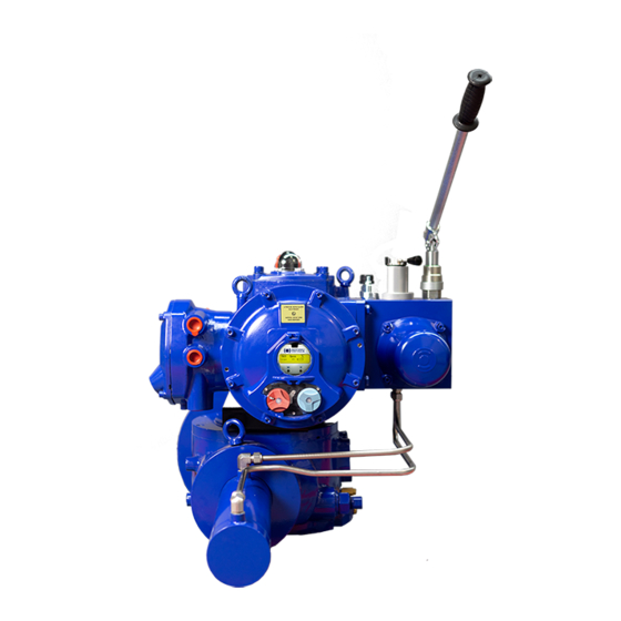
English Operation by Hydraulic Manual Override An optional, manually operated override is available to operate the actuator in the event of a loss of electrical supply to pump/motor. When supplied, a pump with a handle is located on or near the power unit. - Page 61 English When the valve is open Firstly turn the manual override lever towards the manual override indication/needle valve. Then open the needle valve and by doing so the oil will be drained off to the reservoir and the valve will close. When the valve is closed ...
- Page 62 English WARNING The actuator cannot be operated electrically when in manual operation mode and will not respond to emergency shutdown (ESD) signals until electrical operation mode is selected again.
-
Page 63: Adjustment For Limit Switches
English Adjustment for limit switches The cams actuating the limit switch are mounted on the shaft which is coupled to the actuator shaft directly and the actuator shaft in turn is connected to the valve. So as the valve opens/close the actuator shaft rotates thereby rotating the cam shaft thus actuates the mechanical switches mounted inside the enclosure. -
Page 64: Open Switch Adjustment
English Open Switch Adjustment Move the valve/Actuator to the fully open position and locate the uppermost switch cam. To locate the cam, push the cam down and rotate until the uppermost switch operates; and release the cam. The switch is now set. Close Switch Adjustment ... -
Page 65: Removal Of Terminal Block And Cable Connections
English Removal terminal block Cable Connections Removal of terminal cover There are 7 cable entries through the terminal cover which have a thread specification as per the ordering code mentioned on the nameplate for installing the cable gland. To carry out the wiring connection first remove the terminal cover by unbolting the bolts with the help of suitable Allen key. - Page 66 English WARNING Do not open the terminal cover when an explosive atmosphere is present. Ensure that the power supply is cut off before removing the terminal cover.
-
Page 67: Fse For On/Off Application
English FSE for ON/OFF Application Preconditions Power fail to stayput ESD fail close Description SOV01: DCV used for priming the pump. SOV02: DCV used to close the actuator in the auto mode. SOV03: DCV used as the ESD valve. ... - Page 68 English In case of ESD fail the SOV03 is de-energized and the actuator closes. In case the actuator needs to be opened during power failure the MOV01 (selector valve) is switched to the manual mode & then the actuator can be opened using the hand pump by pumping manually.
- Page 69 English Hydraulic circuit diagram...
- Page 70 English Electrical circuit diagram...
- Page 71 English Maintenance and Troubleshooting General maintenance Every BERNARD CONTROLS actuator has been fully tested before dispatch to give years of trouble-free operation provided it is installed and commissioned in accordance with the instructions given in this publication. The FSE actuator’s non-intrusive enclosure provides complete protection for the actuator components.
- Page 72 English Replacement of the filter To replace the filter, unscrew the filter with the help of a suitable spanner. After completely removing the filter from the manifold, clean the filter cartridge and visually inspect the same and its O- rings for any damage.
- Page 73 English Replacement of the hydraulic fluid Check for any loss of hydraulic fluid. This can be done by removing the oil fill plug when the electrical power is cut off from the actuator. The fluid level should be at maximum level as per the dip stick marking.
Need help?
Do you have a question about the FSE Series and is the answer not in the manual?
Questions and answers