Table of Contents
Advertisement
Advertisement
Table of Contents

Related Manuals for Bernard Controls AQ Logic Series


Summary of Contents for Bernard Controls AQ Logic Series
- Page 1 AQ Logic Start-Up guide RANGE Start Up Guide SUG_17004 EN - Ind. B Art : 5100549...
-
Page 3: Table Of Contents
English TABLE OF CONTENTS SAFETY ---------------------------------------------------------- 5 DELIVERY, STORAGE AND MAINTENANCE ------------------- 5 Delivery Storage Maintenance ACTUATOR INSTALLATION ------------------------------------ 7 Fastening actuator on the valve Opening the control compartment Electrical wiring Closing the control compartment ACTUATOR CONTROLS --------------------------------------- 14 Control panel Control modes Local control with Control panel Local control with Smartphone application... - Page 4 English Set Remote commands inputs Set Analog Input / Output (OPTION) 5.10 Set Relays configuration 5.11 Setting Forced local mode in Remote mode OPERATION --------------------------------------------------- 48 Emergency handwheel operation Local control operation APPENDIX ----------------------------------------------------------- 49 Starting with BC App Alarm and Settings menu tree (options not detailed) III.
-
Page 5: Safety
English 1 SAFETY This device complies with current applicable safety standards. Installation, maintenance, and use of this unit require a skilled and trained staff. Please carefully read this whole document before mounting and starting-up the actuator. 2 DELIVERY, STORAGE AND MAINTENANCE 2.1 Delivery AQ actuators are delivered in a cardboard box of a size equivalent to the actuator and sit in a cardboard wedge. -
Page 6: Maintenance
English What to check after storage 1. Visually check the electrical equipment. 2. Manually operate buttons, selectors, etc., to ensure their proper mechanical functionality. 3. Manually operate the actuator for a few travels. What to check on pre-installed actuators If you expect a long period between actuator mounting and electrical wiring: 1. -
Page 7: Actuator Installation
English 3 ACTUATOR INSTALLATION 3.1 Fastening actuator on the valve Actuator should be secured directly to the valve using proper bolts or via a proper interface. After assembly, the actuator can operate in any position. You can modify your display orientation ... - Page 8 English 3.2.1 Changing closing direction indication As a standard, AQ actuator is configured to close clockwise. If the actuator must close counter-clockwise, you can change the orientation of the position indicator cap. This change requires to have the actuator software set ...
-
Page 9: Electrical Wiring
English 3.3 Electrical wiring Ensure wires are not supplied with electric power before wiring is finished and the control compartment is closed. If you need to open control compartment, previously cut off power supply to the actuator. 3.3.1 Components 1 - Position indicator 6 - Torque limiter 2 - Mainboard 7 –... - Page 10 English 3.3.2 Connection and preliminary tests First install cable glands, then connect wires on the terminal blocks. How to install cable glands For each cable entry used 1. Remove plug from the cable entry with 19mm (M16 entry) or 23mm (M20 entry) open-end wrench.
- Page 11 English Internal ground terminal The ground terminal is a metal tab with a fixation hole located under the terminal board at its bottom left (see following picture). How to wire actuator The wiring must be done according to the wiring diagram of your actuator.
- Page 12 English 3.3.3 Power supply board Power supply board supplies actuator with electrical power. Power characteristics are factory set according to your order. Fuse The fuse is located at the upper left angle of the board (see picture). Its characteristics are the following: Fuse size (mm) 6.3×32 Fuse current...
-
Page 13: Closing The Control Compartment
English 3.3.5 Positioner board (OPTION) Positioner board is assembled on the main board. You can select either mA or V using the small switch at the base of the board according to your input signal. 3.3.6 Heating resistor Each actuator includes a heating resistor. As soon as the actuator is installed in the field, it is recommended to supply the resistor to prevent condensation. -
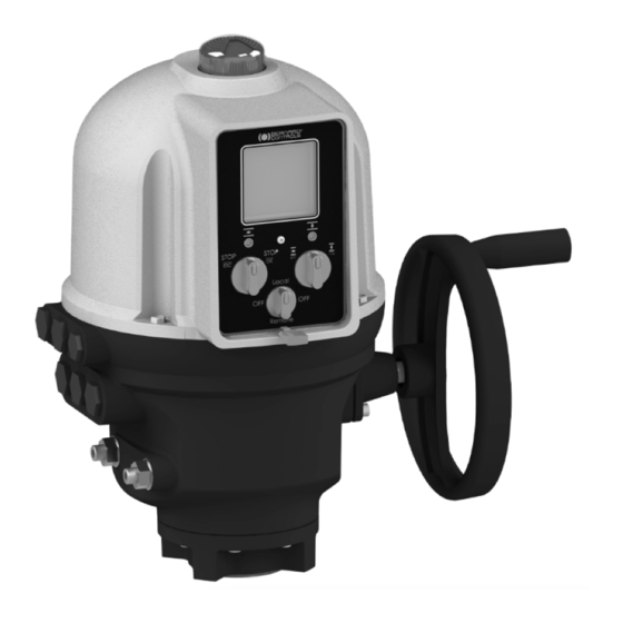
Page 14: Actuator Controls
English 4 ACTUATOR CONTROLS 4.1 Control panel Display LED 2 LED 1 Open / close & navigation knob Stopping & validation knob Control mode selector AQ Logic control panel consists of a screen, 2 control knobs, 1 control selector and 2 configurable LEDs. Screen Screen displays operating status or Logic menu Control selector allows to choose the control mode:... -
Page 15: Control Modes
English 4.2 Control modes AQ logic can be controlled locally or remotely. Mode is set using Control selector on the control panel. It can be locked using a padlock located at the bottom of control panel. Modes are: Local mode with control panel or Smartphone via Bluetooth® connection ... - Page 16 English 4.3.2 Settings Menu screen has 2 main sections… Alarms and warnings Messages are of 2 types identified by icon for warnings or icon alarms. See complete list in appendix III. Settings that allows you to check or change the settings of the actuator: valve tag, password, torque limits, ®...
-
Page 17: Local Control With Smartphone Application
English 4.4 Local control with Smartphone application Using the Bluetooth® connection of your actuator, you can operate it with Bernard Control smartphone application (BC App). ® Bluetooth is active on the actuator at delivery. Using the Local control with BC App requires to have Bluetooth® activated on your smartphone You need first to download the application, install it on your phone, then connect to your actuator by entering an access code. - Page 18 English 4.4.2 Main menu You can access the main menu anytime by tapping on From main menu, you can access… Actuator Operation Diagnostic & status Actuator settings Quit Account data Assistance info 4.4.3 Settings screen From the main menu, you can access the settings. Menu screen has 2 main sections…...
-
Page 19: Remote Controls
English 4.5 Remote controls The AQ Logic remote control system can be operated using an external or an internal voltage supply. The input circuits are fully opto-isolated. The self-hold pulse command system requires 4 connecting wires on the client terminal strip: Common, STOP, OPEN and CLOSE. - Page 20 English 4.5.2 Auxiliary remote controls Dry contact control Voltage control S - Stop S - Stop C - Close C - Close O - Open O - Open A jumper must be fitted Remote control can use either in AC across customer terminal 9- or DC voltage : ...
-
Page 21: Analog Input / Output (Option)
English 4.6 Analog Input / Output (OPTION) 4.6.1 Analog signal types Some actuator configurations can perform control functions in response to a control signal. Input impedance Possible signals (ohms) Positioner board switch 4-20 mA setting (see §3.3.5): 0-20 mA for signals in mA, the 4-12 mA switch must be on mA 12-20 mA... -
Page 22: Commissionning
English 5 COMMISSIONNING This section describes the commissioning with the Control panel, except otherwise mentioned. You can set the same settings with App from the menu Settings > Commissioning of Actuator on valve. In order to modify the actuator settings, control mode must be set to Local mode. - Page 23 English To enter the actuator menu, you need first to enter the access code. If you are the end-user: At the first on-site start, we strongly advise you to modify the ® default Bluetooth access codes. To proceed to these changes, please follow the 2 following procedures.
- Page 24 English How to reset the access codes If the actuator is ON for more than 10 minutes, switch it OFF then switch it ON. When on the operation display, Hold both left knob and right knob during 10s. Reset password screen appears. Select YES then validate with OK.
- Page 25 English ® How to change the Bluetooth access codes with Control panel ® Bluetooth access codes can only be changed using Read & Write mode. 1. Go to Settings > Actuator’s access code. Actuator’s access codes screen appears. 2. Depending on the access code you need to change: ...
- Page 26 English ® How to change the Bluetooth Access codes with BC App 1. Go to Main Menu 2. Select Settings > Actuator passwords and security. 3. The Actuator passwords & security menu appears. 4. Select the Password you want to change. 5.
-
Page 27: Set Closing Rotation Direction
English 5.2 Set closing rotation direction Default setting for closing direction is clockwise. According to your needs, you may have to change your closing direction. How to change closing direction Enter the menu, then go to Settings > Actuator commissioning > Set closing rotation direction. Choose the closing rotation direction required, Clockwise or ... -
Page 28: Set Torque Limits
English 5.4 Set torque limits This setting allows to set torque limits at main steps of the travel: at the beginning (Break), during the travel (Run) and at the end of the travel (End). Limits are: In closing direction: Break to Close (BTC), Run to Close (RTC), End to Close (ETC), Tight zone... - Page 29 English How to set torque limits 1. Enter the menu, then go to Settings > Commissioning 2. Select Set torque limits and validate with OK. 3. Select closing or opening direction and validate with OK. Torque limits screen appears. 4.
- Page 30 English 5. To set Break limits To set No limit, use on 1 digit, then ESC. To set another value, validate 1 digit with OK then set 2 & 3 with then validate each with OK. ...
-
Page 31: Setting Open And Closed Positions
English 5.5 Setting open and closed positions 5.5.1 Setting end positions AQ Logic features position sensor. To set end positions, you have first to record OPEN and CLOSED positions one after the other, depending on the first one set. Mechanical stops must not be used as travel limits. - Page 32 English 4. Validate Confirm with OK. The setting screen for the opposite setting appears. 5. Open your valve using the opening knob An indication of stroke angle appears. You can validate with OK at any moment. If the Stroke set is too small, the opposite error screen appears.
- Page 33 English 5.5.2 Setting mechanical stops The actuator is factory-set for a 90°travel. Mechanical stops (1: counter- clockwise – clockwise) mechanically block rotation to protect the valve in case of over- travel case handwheel operation. They are factory-set. They can be set on the actuator or on the gearbox if a gearbox is fitted on the actuator.
-
Page 34: Set Display Orientation
English 5.6 Set display orientation Your display orientation can be modified according to the physical orientation of your actuator. How to change orientation of your display 1. Enter the menu, then go to Settings > Buttons & Display. The following screen appears. 2. -
Page 35: Set Leds Configuration
English 5.7 Set LEDs configuration Your LEDs configuration can be adjusted according to the standard of your country. How to set LEDs configuration 1. Enter the menu, then go to Settings > Buttons & Display. The Buttons & Display screen appears. Go down in the menu to LED color. -
Page 36: Set Remote Commands Inputs
English 5.8 Set Remote commands inputs 5.8.1 Set Auxiliary Remote commands To set Auxiliary Remote commands, go to Settings > Digital inputs – Remote Commands. The following settings are available:... - Page 37 English 5.8.2 Set Priority for remote commands Priority allows to reverse the direction of travel when an operation is in progress without having to stop actuator. How to set priority for remote command Enter the menu then go to Settings > Remote commands. The Remote Commands screen appears.
-
Page 38: Set Analog Input / Output (Option)
English 5.9 Set Analog Input / Output (OPTION) To set analog input/ouput, go to Settings > Analog input/output and set the different options necessary. 5.9.1 Activate positioner If present, the actuator can operate as a positioner using a proportional command, such as a 4-20 mA analogue signal. How to activate positioner 1. - Page 39 English 5.9.2 Set Input signal How to set Input Signal 1. From Analog Input/Output menu, enter Input Signal Type. The Input Signal type screen appears. 2. For Signal Type and Signal Direction settings: a. Select the setting to adjust and validate with OK. The corresponding setting screen appears.
- Page 40 English 5.9.3 Set Positioner feedback signal How to set Positioner Feedback signal 1. From Analog Input/Output menu, enter Positioner feedback signal. The Positioner feedback signal screen appears. 2. For Feedback Signal Type, Feedback Signal Direction and Feedback Signal Wiring settings: a.
- Page 41 English 5.9.4 Set Deadband The deadband value is the maximum allowable difference between the signal and the actuator position when no action occurs. This setting is made at the factory, but it is possible to adjust it. If the deadband is too narrow, the actuator could hunt, moving back and forth around the expected position without stabilizing;...
- Page 42 English 5.9.5 Fail-Safe position When a 4-20 mA input signal is used, it is possible to set up a fail- safe position for use if the control signal is lost. This function cannot be used with 0-20 mA signals, as the ...
-
Page 43: Set Relays Configuration
English 5.10 Set Relays configuration Available relays can be configured for specific functions. How to set relays configuration Following procedure runs through the procedure for the 3 standard relays installed. Apply the same procedure for optional relays. Enter the menu then go to Settings > Remote feedbacks. The Remote Feedbacks screen appears. - Page 44 English Select an option in the list For standard relays, options available are: Relay 1 Relay 3 Information Faults Valve open Valve open Stopped in intermediate position Valve closed Relay 2 Motor thermal Torque limiter ...
- Page 45 English 5.11 Setting Forced local mode in Remote mode You need 2 steps to be able to use Forced local mode: 1. Allowing switch to Local mode with Local control 2. Switch to Local mode with App 5.11.1 Allowing / Inhibit switch to Local control How to allow or inhibit switch to Local control 1.
- Page 46 English 5. Go to Save and validate it. The confirmation screen appears. 6. Select YES and validate. 5.11.2 Switching to Local control with App You can only proceed to this operation if Control selector is on Remote on the actuator and actuator set on Switch to local mode allowed.
- Page 47 English 2. Tap on Edit. The App asks for confirmation. 3. Tap on Switch to Local Mode. Remote mode becomes Local mode. You can now operate your actuator as if it is set on Local mode. To get back to Remote mode, simply tap again on the Edit button.
-
Page 48: Setting Forced Local Mode In Remote Mode
English 6 OPERATION 6.1 Emergency handwheel operation AQ actuators feature a handwheel for emergency operation. To avoid potentially harmful turning protruding parts during electrical operation, AQ handwheels feature a foldable handle: you can fold it during electrical operation and unfold it if you need to operate the actuator manually. -
Page 49: Appendix
Installing the application An Internet connection is required on your smartphone. 1. Go to your app store and search for “Bernard Controls”. 2. Once retrieved, download and install BC App. Once installed, start the App. Log in or follow free account creation screen sequence if it is your first start. - Page 50 English Connecting to your actuator Once account is confirmed, your smartphone is ready to connect to your actuators. Connection to actuators is achieved with Bluetooth ® 1. Start the App and log in your account. 2. Once logged, App will start to scan for actuators nearby. 3.
-
Page 51: Alarm And Settings Menu Tree (Options Not Detailed)
English II. Alarm and Settings menu tree (options not detailed) Level 1 Level 2 Level 3 Alarm & Warnings Settings Valve tags Valve tag Location and process Actuator commissioning Set closing direction Closing & Opening Type Set torque limits Set closed position Set open position Remote commands Auxiliary remote commands 1... -
Page 52: Alarms And Warnings List
English III. Alarms and warnings list System alarms Warnings (Fault Relay) Locked motor in open direction Overtravel Locked motor in close direction Activity memory fault Torque sensor fault Excessive number of starts Position sensor fault Auxiliary power supply fault for external circuits Abnormal rotation direction in Opening... - Page 53 English NOTES...
- Page 54 English...
- Page 56 Tel. : +33 (0)1 34 7 71 00 / Fax : +33 (0)1 34 07 71 01 / mail@bernardcontrols.com CONTACT BY OPERATING AREAS > AMERICA > EUROPE > INDIA, MIDDLE EAST & AFRICA NORTH AMERICA BELGIUM AFRICA BERNARD CONTROLS UNITED STATES BERNARD CONTROLS BENELUX BERNARD CONTROLS AFRICA HOUSTON NIVELLES (BRUSSELS) ABIDJAN - IVORY COAST inquiry.usa@bernardcontrols.com inquiry.belgium@bernardcontrols.com inquiry.africa@bernardcontrols.com...
Need help?
Do you have a question about the AQ Logic Series and is the answer not in the manual?
Questions and answers