Bernard Controls SQX Series Instructions For Start-Up
Hide thumbs
Also See for SQX Series:
- Instructions for start-up (23 pages) ,
- Instructions manual (79 pages)

Related Manuals for Bernard Controls SQX Series


Summary of Contents for Bernard Controls SQX Series
- Page 1 INSTRUCTIONS FOR START-UP SQX & STX RANGES - ‘SWITCH’ VERSION MANUEL DE MISE EN SERVICE GAMMES SQX ET STX - VERSION ‘SWITCH’ (ATEX & IECEx) Gamme Range...
-
Page 2: Table Of Contents
CONTENTS 1 Safety information Page 3 1.1 Marking Page 3 1.2 Installation Area Page 4 1.3 Cautions for electrical connection Page 4 1.4 Operation Page 6 1.5 Maintenance Page 6 1.6 Electrical and temperature parameters Page 6 1.7 Special operation conditions including unconrrect practices Page 6 1.8 List of applicable standards Page 7... -
Page 3: Safety Information
BERNARD CONTROLS cannot be judged responsible for the non-respect of these rules. Our actuators have been designed for a use in explosive atmospheres: group II - category 2 in presence of vapour, fog or gas (G) or dust (D). -
Page 4: Installation Area
1.2 INSTALLATION AREA This actuator is a category 2 explosion-proof equipment and can be used in the following areas depending on the marking : Actuator type STX.., Protection Ex d, Ex de, Ex tb Ex d , Ex de, Ex tb Category 2 (EPL Gb, Db) 2 (EPL Gb, Db) - Page 5 sure not to degrade the gaskets while closing the cover. Cable entries shall provide a level of protection equal or higher than the one indicated on the actuator identification plate. The user shall ensure a regular cleaning of the product housing to avoid dust build-up. Overheating A motor thermal protection switch (refer to actuator electric diagram) is located in the motor.
-
Page 6: Operation
Dimensions of explosion proof joints are specific. Consult BERNARD CONTROLS for information. 1.6 ELECTRICAL AND TEMPERATURE PARAMETERS The power supply voltage and frequency are indicated on the identification tag and (or) on the electric wiring diagram. -
Page 7: List Of Applicable Standards
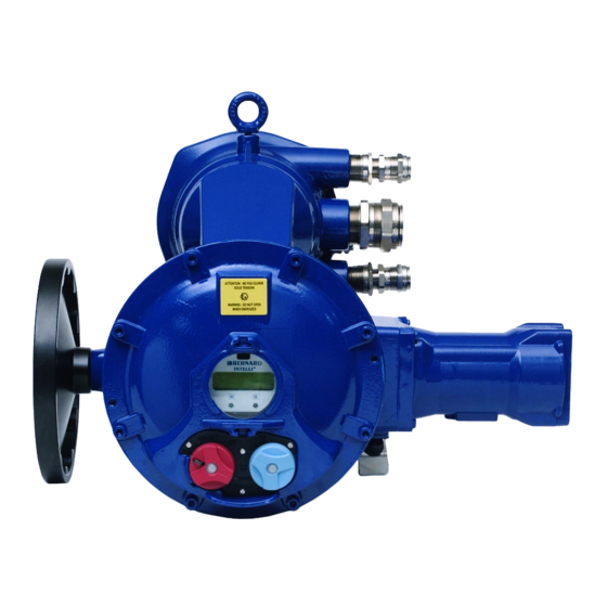
1.8 LIST OF APPLICABLE STANDARDS EN60079-0 (2012) + A11 (2013), EN60079-1(2007), EN60079-7 (2007), EN60079-31 (2009), EN13463-1 (2009), EN 13463-5 (2011), IEC60079-0 (2011), IEC60079-1 (2007), IEC 60079-7 (2006), IEC60079-31 (2008) 2 PRODUCT OVERVIEW Terminal compartment Emergency handwheel Power and controls connection Manual override STX and SQX actuators incorporate a handwheel for manual control with an automatic clutch sys- tem with motor-drive priority. -
Page 8: Actuator On Valve Assembly
2. If stored for more than one year: • Long-term storage causes the consistency of the grease to change. To avoid any grease-drying problem, do some rotations of the actuator several times a year by using motor or manual override. •... -
Page 9: Setting Of Mechanical Stops And Travel Limit Switches
In the same way, check that the closing electrical command as well as the «CLOSED» travel limit switch are working correctly, d) Operate an electrical opening. Press manually on the «OPEN» torque limit switch ; the motor should stop. In the same way, operate an electrical closing check that the «CLOSED» torque limit switch is wor- king correctly, If any misfunction was detected at this stage, please check the overall wiring. -
Page 10: Setting Of Torque Limit Switches
8 SETTING OF TORQUE LIMIT SWITCHES Actuators are set and tested in accordance with the torque stated on purchase orders. If no torque is specified, the actuator is supplied with torque springs set to the nominal torque (refer to our Technical Handbooks). SQX and STX6 models IMPORTANT: the torque limit switch design of SQX/STX6 actuators gives a short duration contact only (signal has to be memorised). -
Page 11: 11 "Tam" Position Feedback Transmitter
marking while driving the potentiometer screw. Adjust the potentiometer so that the resistance value exceeds 0 Ohm and regularly increases then turn backwards to reach a value as close to 0 Ohm as possible. Drive the actuator to the open position and write down the resistance value corresponding to the 100% position. -
Page 12: Maintenance
Settings Connect a milliampermeter at the place of burden. - Always start by adjusting the 0/4mA. - Drive actuator to the position corresponding to the 0/4 mA (closed in standard), - Hold the pinion located just under the plate with the «0% position» marking while driving the potentiometer screw. -
Page 13: Marquage
1.1 MARQUAGE ATEX protection IECEx protection IEx protection antidéflagrante « d » antidéflagrante « d » antidéflagrante « d » BERNARD CONTROLS BERNARD CONTROLS BERNARD CONTROLS Nom et adresse 4 rue d’Arsonval 95505 4 rue d’Arsonval 95505 4 rue d’Arsonval 95505... -
Page 14: Zone D'utilisation
1.2 ZONE D’UTILISATION Ce matériel antidéflagrant est de catégorie 2 et peut être utilisé dans les zones suivantes : Type de servomoteur STX.., Protection Ex d, Ex de, Ex tb Ex d , Ex de, Ex tb Catégorie 2 (EPL Gb, Db) 2 (EPL Gb, Db) Zones 1 ou 2... - Page 15 La visserie des enveloppes antidéflagrantes doit être de qualité minimum 8.8 ou en inox de résistance à la rupture de 70 daN/mm² mini. Pour l’utilisation dans les atmosphères poussiéreuses, vérifier le bon état des joints d’étanchéité des cou- vercles et veiller à ne pas détériorer les joints lors de la fermeture. Les entrées de câble devront avoir un degré...
-
Page 16: Utilisation
La dimension des joints antidéflagrants étant spécifique au matériel consulter BERNARD CONTROLS pour information. 1.6 PARAMETRES ELECTRIQUES ET TEMPERATURES La tension et la fréquence d’alimentation sont indiqués sur la plaque signalétique et (ou) sur le schéma... -
Page 17: Liste Des Normes Appliquées
1.8 LISTE DES NORMES APPLIQUEES EN60079-0 (2012) + A11 (2013), EN60079-1(2007), EN60079-7 (2007), EN60079-31 (2009), EN13463-1 (2009), EN 13463-5 (2011), IEC60079-0 (2011), IEC60079-1 (2007), IEC 60079-7 (2006), IEC60079-31 (2008) 2 PRÉSENTATION Raccordement électrique Volant de commande manuelle Connexion électrique puissance et contrôle Comande manuelle Les servomoteurs STX &... -
Page 18: Raccordement Électrique
4 MONTAGE SUR VANNE Le servomoteur doit être boulonné sur l’appareil à motoriser. Les servomoteurs BERNARD CONTROLS sont graissés à vie et peuvent fonctionner dans n’importe quelle position. Cependant, les presse-étoupes ne devraient par être orientés vers le haut (étanchéité) et le moteur pas placé en position basse (accumulation de condensation potentielle). -
Page 19: Réglage Des Butées Mécaniques Et Des Contacts De Fin De Course
c) Actionner la commande électrique d’ouverture. Vérifier que le sens de rotation du servomoteur est correct. Actionner manuellement le contact de fin de course «OPEN» (ouvert) ; le moteur doit s’arrêter. Vérifier de la même manière la commande électrique de fermeture et le contact de fin de course «CLOSED»... -
Page 20: Réglage Du Limiteur De Couple
8 REGLAGE DU LIMITEUR DE COUPLE Le servomoteur est livré avec un système limiteur d’effort étalonné en atelier. Son réglage est effectué suivant les valeurs spécifiées à la commande ou, par défaut, à 100% du couple nominal du servomoteur (cf. nos Guides Techniques). Modèles SQX et STX6 IMPORTANT: Les microrupteurs limiteurs de couple des SQX donnent un contact à... -
Page 21: Transmetteur De Position Type "Tam" (Option)
Le réglage du zéro du potentiomètre s’effectue à l’aide de la vis repérée «0% position». Amener le servomoteur en position fermée. La mesure de résistance s’effectuera entre les bornes 16 et 17. Tout en maintenant manuellement en position la pignonnerie située juste sous la plaque marquée «0% position», tourner la vis du potentiomètre jusqu’à... -
Page 22: Maintenance
Réglages Brancher un milliampèremètre avec ou sans charge pour lire le courant de sortie. - Le réglage doit toujours commencer par le 0/4mA. - Amener le servomoteur dans la position qui doit correspondre au signal 0/4mA (en standard c’est la fin de manoeuvre de l’organe entrainé dans le sens horaire ou position fermée). - Tout en maintenant manuellement en position la pignonnerie située juste sous la plaque marquée «0% position», tourner la vis du potentiomètre jusqu’à... -
Page 23: Torque Adjustment Tables
13 TORQUE ADJUSTMENT TABLES TABLEAUX DE CORRESPONDANCE DES COUPLES Please note: According to the outpout speed, the nominal torque can be different for each reference. The given values are indicative, only a setting on testing bench warrants the device accuracy. The precision is +/-10%. Attention: Selon la vitesse de sortie, le couple nominal peut être différent sur chaque référence. - Page 24 13.3 STX40 Nominal Torque Couple Nominal 400 Nm 360 Nm 320 Nm 280 Nm 240 Nm 200 Nm 160 Nm 400 Nm 100 % 90 % 80 % 70 % 60 % 50 % 40 % 350 Nm 310 Nm 270 Nm 230 Nm 190 Nm...
- Page 25 NOTES...
- Page 26 NOTES...
- Page 28 BC GROUP Exhaustive list of agents and BELGIUM RUSSIA distributors on BERNARD CONTROLS BENELUX BERNARD CONTROLS RUSSIA BRUXELLES MOSCOW www.bernardcontrols.com inquiry.belgium@bernardcontrols.com inquiry.russia@bernardcontrols.com inquiry.holland@bernardcontrols.com Tel. +7 499 251 06 54 Tel. +32 (0)2 343 41 22 SINGAPORE BERNARD CONTROLS SINGAPORE CHINA...
Need help?
Do you have a question about the SQX Series and is the answer not in the manual?
Questions and answers