Table of Contents
Advertisement
Quick Links
English translation of the original operating
instructions
Documentation
It is imperative to read the operating instruc-
tions prior to commissioning!
This document as well as all documents in-
cluded in the appendix is not subject to any
update service!
Subject to technical changes.
Operating Instructions
VU / VH Series
VU 20 - 1600
VH 20 - 1600
Liquid Ring Vacuum Pumps
Speck Pumpen Vakuumtechnik GmbH
Regensburger Ring 6 – 8, 91154 Roth / Germany
PO Box 1453, 91142 Roth / Germany
Phone:
+49 (0) 9171 809 0
Fax:
+49 (0) 9171 809 10
E-mail:
info@speck-pumps.de
Internet:
www.speck-pumps.de
Issue:
Supersedes issue:
10/2010
06/2010
Doc./ Item no.:
1096.0799
Advertisement
Table of Contents

Related Manuals for Speck pumpen VU Series


Summary of Contents for Speck pumpen VU Series
- Page 1 VU 20 - 1600 VH 20 - 1600 Liquid Ring Vacuum Pumps English translation of the original operating Speck Pumpen Vakuumtechnik GmbH instructions Regensburger Ring 6 – 8, 91154 Roth / Germany PO Box 1453, 91142 Roth / Germany Documentation...
-
Page 2: Table Of Contents
Operating Instructions Index 5.6.1 Dimensioning supports and connections ....15 Index ................... 2 5.6.2 Specifying nominal diameter ........15 5.6.3 Specifying pipe lengths........... 16 Important basic information ..........4 5.6.4 Changes in cross-section and direction .... - Page 3 Operating Instructions 9.1.2 Operating liquid ............39 9.1.3 Switching frequency ..........39 General technical data ........... 39 9.2.1 Weight ..............39 9.2.2 Sound level ............. 39 9.2.3 Drive power ............39 ...
-
Page 4: Important Basic Information
Warranty and liability Essentially the “General Conditions of Sale and Delivery” of Speck Pumpen Vakuumtechnik GmbH applies. Duplication or transfer of these operating instructions to third They were provided to the operator at the time of contract con- parties requires written approval of the manufacturer. -
Page 5: Target Groups
Operating Instructions 1.1 Target groups Target group Task Operator ► Keep these instructions available at the location of the system, also for later consultation. ► Advise staff to read and observe these instructions and the provided documents, particularly the safety precautions and warnings. -
Page 6: Warnings And Symbols
Operating Instructions 1.3 Warnings and symbols Warning Security level Consequences of non-observance imminently hazardous situation death, severe personal injuries DANGER potentially hazardous situation death, severe personal injuries WARNING potentially dangerous situation minor personal injuries CAUTION potentially dangerous situation material damage CAUTION Tab. -
Page 7: Safety
Operating Instructions Safety The manufacturer does not accept liability for damage 2.3 General safety instructions resulting from non-observance of the overall documenta- tion. The following provisions must be observed prior to execut- ing any works. 2.1 Intended use 2.3.1 Product safety •... -
Page 8: Obligations Of The Staff
Operating Instructions 2.3.2.3 Safety devices 2.5 Special risks • Provide for the following safety devices and ensure their 2.5.1 Potentially explosive area proper functioning: • ( ATEX additional instructions) for hot, cold and moving parts: on-site protection against contact with the pump/aggregate 2.5.2 Dangerous media to be pumped ... -
Page 9: Design And Functioning
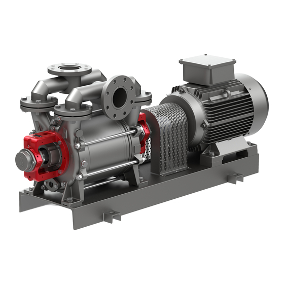
Operating Instructions Design and functioning 3.2 General description The pumps of the VU series are horizontal liquid ring vacuum 3.1 Marking pumps with a single stage and radial suction/pressure connec- tion. The internal control of the media to be pumped is realized 3.1.1... -
Page 10: Design And Functional Principle
Operating Instructions The VH 20 - 1600 types are two-stage liquid ring vacuum pumps 3.3 Design and functional principle in base plate version. The vacuum pump is operated in accordance with the liquid ring The electrical drive is connected to the pump shaft (3) via a principle. -
Page 11: Transport, Storage And Disposal
Operating Instructions Transport, storage and 4.1.3 Transport with lifting gear disposal DANGER Risk of death or contusions from falling goods to be trans- The following accident prevention regulations have to be ported! observed prior to following transport and handling regula- tions: ►... -
Page 12: Storage
Operating Instructions • Fill in preserving agent into the open inlet nozzle. Observe 4.2 Storage the filling volumes. (Filling volumes for preservation, page 45). Pumps/aggregates treated by the factory have been provided with an anticorrosive coating. When properly stored indoors, the •... -
Page 13: Removing Preserving Agent
Operating Instructions 4.4 Removing preserving agent Only required for treated pumps/aggregates. CAUTION Risk of bearing damage caused by excessive water pres- sure or splash water! ► Do not treat bearing areas with water or steam jet. CAUTION Risk of seal damage caused by improper cleaning agents! ►... -
Page 14: Set-Up And Connection
Operating Instructions Set-up and connection 5.2 Set-up with foundation Only possible with base plate. For pumps/aggregates in potentially explosive areas ( ATEX additional instructions) CAUTION CAUTION Risk of material damage caused by distortion of the base plate! Risk of material damage caused by contamination! ►... -
Page 15: Set-Up Without Foundation
Operating Instructions Set-up without foundation 5.5 Motor installation With base plate Only necessary if aggregate set-up is completed at the installation site. Auxiliary means, tools, material: wrench CAUTION spirit level Risk of material damage caused by knocks and bumps! ►... -
Page 16: Specifying Pipe Lengths
Operating Instructions 5.6.3 Specifying pipe lengths 5.7.3 Installing pressure pipe Dimension the suction, pressure and operating liquid pipes Remove the transport and sealing covers from the as short as possible. pump/aggregate. Increase the pipe cross-sections when using long suction, Install the pressure pipe. pressure and operating liquid pipes. -
Page 17: Motor Adjustment
Operating Instructions Coupling guard has been disassembled. 5.10.2 Checking direction of rotation Take the measurements at the circumference of the cou- pling in two planes with a 90° offset. DANGER Check the light gap towards the outer diameter using a Risk of death from rotating parts! straightedge (1): ... -
Page 18: Operation
Operating Instructions Operation RISK OF ELECTRIC SHOCK For pumps/aggregates in potentially explosive areas ( ATEX additional instructions) Risk of death from electric shock! ► Any electrical works must be carried out by qualified electri- 6.1 Preparations for commissioning cians only. 6.1.1 Identifying pump type ►... -
Page 19: Switch-Off
Operating Instructions 6.2.2 Switch-off WARNING Risk of injuries caused by vacuum or harmful media to be pumped and operating liquid! ► Use protective equipment when carrying out any works on the aggregate. Operating liquid: close fitting. Switch off the motor. Ventilation port (if available): open the fitting. -
Page 20: Closed Circulation Cooling
Operating Instructions Implement the following measures when taking the 6.3.3 Closed circulation cooling pump/aggregate out of operation: ► Switch on the aggregate. Pump/ Measure ► Set the pressure in the operating liquid pipe to a value aggregate is which is 0.1 bar smaller than the compression pressure (Diagram Fig. -
Page 21: Maintenance And Servicing
Operating Instructions Maintenance and servicing In case of leaks: Have the mechanical seal with auxil- iary seals replaced by service staff or the manufac- turer. Check auxiliary operating systems (if available) For pumps/aggregates in potentially explosive areas for proper functioning or have them checked. (... -
Page 22: Preventing Calcification
Operating Instructions 7.4 Preventing calcification 7.5.1 Return to manufacturer Aggregate shut down Calcification results in excessive wear of moistened pump Aggregate depressurized parts and increases the power consumption of the drive. Pump completely drained Area of protective coating ... -
Page 23: Disassembly Of Vu 20/40, Vh 20/40/60
Operating Instructions 7.5.4 Disassembly of VU 20/40, VH 20/40/60 7.5.5 Disassembly of VU 80/140/220 VH 110/140/180 Cross-sectional drawing VU 20/40 Cross-sectional draw- Cross-sectional drawing VU 80 - 220 Cross-sectional ing, page 48 drawing, page 48 Cross-sectional drawing VH 20 - 60 ... -
Page 24: Disassembly Of Vu 300/450, Vh 300/350/400
Operating Instructions Disassembly of mechanical seal (SU 1/2) ( Preparations Disassembly of stage casing and pump shaft for assembly, page 26) Remove the stage casing (110). Push the stationary units of the mechanical seals Remove the pump shaft (211) with the impeller (230). (047/047.1) out of the shaft sealing casings (441). -
Page 25: Disassembly Of Vu 500/600/800/1200/1600
Operating Instructions Disassembly of bearing housing on discharge casing (non- Disassembly of mechanical seal (RU 1) ( Preparations for drive side) assembly, page 26) Loosen the hexagon head screws (901.1), remove the Loosen the hexagon head screws (901.1/901.2), pull bearing cover (360). -
Page 26: Preparations For Assembly
Operating Instructions 10. Disassembly of inter casing of the suction/discharge casing Loosen the hexagon socket head screw (914) in the suction/discharge casing (106/107). Remove the inter casing (137/137.1) from the suc- tion/discharge casing (106/107). Additional steps for VH 500/600/800/1200/1600 ... -
Page 27: Assembly Of Vu 80/140/220, Vh 110/140/180
Operating Instructions Discharge casing and inter casing Verify unobstructed movement of the pump. Manually Clamp in the bearing housing (330) and the pump rotate the pump shaft. shaft (211) with the drive side pointing up. Additional steps for VH 60 ... -
Page 28: Assembly Of Vu 300/450, Vh 300/350/400
Operating Instructions Installation of stage casing and pump shaft Installation of bearing housing on discharge casing (non- drive side) Horizontally clamp the discharge casing (107) (inter casing on top). Force the bearing cover (360.2) into the bearing hous- ing (330) and adjust it, fasten it with hexagon head VU 80/140/220 screws (901.1). - Page 29 Operating Instructions Installation of inter casings on suction/discharge casing Installation of mechanical seal (drive side) Moisten the auxiliary seal of the rotating unit (047) with Adjust the inter casing (137) (marks) and force it into lubricant (grease containing PTFE). the suction casing (106).
-
Page 30: Assembly Of Vu 351/451
Operating Instructions 10. Pump adjustment Installation of stage casing and pump shaft Horizontally clamp the discharge casing (107) (inter Position the pump horizontally and adjust it on level casing on top). ground. Insert the complete pump shaft (drive side pointing up) ... -
Page 31: Assembly Of Vu/Vh 500/600/ 800/1200/1600
Operating Instructions Installation of bearing housing on discharge casing (non- Additional steps for VH 800/1200/1600 drive side) Adjust the inter casings (137.1/137.2) (mark), Force the bearing cover (360.1) into the bearing hous- force them into position and compress them. ing (330), adjust it and fasten it with hexagon head Additional steps for VH 500/600 screws (901.1). - Page 32 Operating Instructions Installation of suction casing 10. Pump adjustment Adjust the suction casing (106) (marks) and force it Position the pump horizontally and adjust it on level onto the stage casing (110). ground. Secure the casing bolts (563) and slightly fasten them ...
-
Page 33: Troubleshooting
If the maintenance staff is not able to rectify the defect, the manufacturer has to be informed accordingly. The manufacturer will provide troubleshooting support if he gets a detailed description of the defect. Technical support address Speck Pumpen Vakuumtechnik GmbH Regensburger Ring 6 – 8, 91154 Roth / Germany PO Box 1453, 91142 Roth / Germany... - Page 34 Operating Instructions Defect Cause Rectification Motor protection triggered Short-circuit in the motor winding ► Check the motor winding Motor protection switch has not been correctly ► Check setting/replace the motor protection set/is defective switch Motor overload ► Check/reduce the operating liquid flow rate Excessive backpressure in the outlet nozzle ►...
- Page 35 Operating Instructions Defect Cause Rectification Leaking pump Defective shaft sealing ► Replace the shaft sealing Defective casing sealing ► Provide the vacuum pump with new sealing Worn-out casing components ► Replace the affected components Loosened connecting screws/screw plugs ► Tighten the screws, replace the sealing Pump does not run Excessive operating liquid flow rate ►...
-
Page 36: Technical Data
Operating Instructions Technical data 9.1 Operating limit values Inlet pressure Compression pressure Pressure difference Medium to be pumped Operating liquid Speed Switching frequency VU 20/40 Pressure [mbar] Operating liquid Min. inlet pressure Temperature [°C] Perm. - Page 37 Operating Instructions VU 351/451 Pressure [mbar] Operating liquid Min. inlet pressure Temperature [°C] Perm. compression pressure 1500 Max. Perm. pressure difference Min. - 10 Max. 1500 Density [kg/m Min. Max. 1200 Medium to be pumped Viscosity Temperature [°C] Max. Speed [min Saturated Max.
- Page 38 Operating Instructions VH 110/140/180 Pressure [mbar] Operating liquid Min. inlet pressure Temperature [°C] Perm. compression pressure 1500 Max. Perm. pressure difference Min. - 10 Max. 1500 Density [kg/m Min. Max. 1200 Medium to be pumped Viscosity Temperature [°C] Max. Speed [min Saturated Max.
-
Page 39: Media To Be Pumped
Operating Instructions 9.1.1 Media to be pumped 9.2.2 Sound level • Dry and wet gases which are not explosive, inflammable, Type 1m measured surface sound aggressive or toxic pressure level • Air or air-steam mixtures L [dB (A)] * which are free of solids 50 Hz 60 Hz... -
Page 40: Operating Liquid
Operating Instructions 9.2.4.3 Filling volume Type Rated motor Rated motor Direction Type Flow rate Max. liquid Filling vol- power speed of rotation [l/min] delivery ume up to [kW] [min as seen middle of the 80 mbar/ from the shaft 15 °C 50 Hz 60 Hz 50 Hz... -
Page 41: Operating Connections
Operating Instructions 9.2.6 Operating connections Type Process water connection Suction connection Pressure connection Size Shape Size Shape Size Shape VU 20/40 G 3/8“ Thread G 1 1/4“ Thread G 1 1/4“ Thread VH 20/40/60 VU 80/140 G ½“ Thread DN 40 Flange DN 40 Flange... -
Page 42: Tightening Torques
Operating Instructions 9.2.10.4 For screw plugs 9.2.10 Tightening torques ► Tighten the screws by means of a torque wrench. 9.2.10.1 For screws and nuts The following values apply to new screw plugs (St, Ms) in ► Tighten the screws by means of a torque wrench. cast-iron casings (EN-GJL-250, CuZn). -
Page 43: Conical Pipe Fittings
Operating Instructions 9.2.10.6 Impeller nuts 9.4 Permissible forces / torques acting ( Cross-sectional drawing, Item 922) on the pump nozzles Type Dimensions Tightening torque Nominal width Pump nozzle [Nm] VU/VH 80 – 220 M 40x1.5 [Nm] DN 6 VH 300 - 350 M 45x1.5 DN 8 VU 351 - 451... -
Page 44: Lubricants
Operating Instructions 9.4.1.3 Impeller position VH 110-1600/VU 80-1600 Type Adjustment dimension [ l ] VH 110-180 226.0 VH 300-400 326.5 VH 500/600 363.5 VH 800-1600 507.0 VU 80-220 226.0 VU 300/450 331.5 Fig. 21 Impeller position VH 110-1600/VU80-1600 VU 351 325.5 VU 451 325.0... -
Page 45: Preserving Agents
Operating Instructions 9.6 Preserving agents Type Filling volume Filling volume Rivolta preserving agent (recommended) or comparable inside system outside system products [ l ] [ l ] Type of Period of Inside/outside Repeat in- VH 20 approx. 2.0 storage storage preservation side/outside... -
Page 46: Appendix
Operating Instructions 10 Appendix The appendix contains: • Dimensions of the individual aggregates (dimension drawings) • Spare parts designation and position (cross-sectional drawings) • Certificate of conformity • EC declaration of conformity 10.1 Dimension drawing VU 20/40 Fig. 22 Dimension drawing VU 20 Fig. -
Page 47: Dimension Drawing Vu 80/140/220
Operating Instructions 10.2 Dimension drawing VU 80/140/220 Fig. 24 Dimension drawing VU 80 Fig. 25 Dimension drawing VU 140 Fig. 26 Dimension drawing VU 220 Manometer connection Designation Explanation Operating liquid connection Sensor connection Drainage (screw plug) Drainage valve connection Ventilation valve connection Tab. -
Page 48: Dimension Drawing Vu 300/450
Operating Instructions 10.3 Dimension drawing VU 300/450 Fig. 27 Dimension drawing VU 300 Fig. 28 Dimension drawing VU 450 Designation Explanation Operating liquid connection Drainage (screw plug) Ventilation valve connection Manometer connection Sensor connection Drainage valve connection Tab. 46 Connections VU 300/450 1096.0799 | VU / VH Series 10/2010... -
Page 49: Dimension Drawing Vu 351/451
Operating Instructions 10.4 Dimension drawing VU 351/451 Fig. 29 Dimension drawing VU 351 Fig. 30 Dimension drawing VU 451 Designation Explanation Operating liquid connection Connection for cavitation protection Drainage (screw plug) Adjusting screw for internal liquid recirculation Ventilation valve connection Tab. -
Page 50: Dimension Drawing Vu 500/600
Operating Instructions 10.5 Dimension drawing VU 500/600 Fig. 31 Dimension drawing VU 500 Fig. 32 Dimension drawing VU 600 Designation Explanation Operating liquid connection Drainage (screw plug) Ventilation valve connection Manometer connection Sensor connection Drainage valve connection Tab. 48 Connections VU 500/600 1096.0799 | VU / VH Series 10/2010... -
Page 51: Dimension Drawing Vu 800/1200/1600
Operating Instructions 10.6 Dimension drawing VU 800/1200/1600 Fig. 33 Dimension drawing VU 800 Fig. 34 Dimension drawing VU 1200 Fig. 35 Dimension drawing VU 1600 Manometer connection Designation Explanation Operating liquid connection Sensor connection Drainage (screw plug) Drainage valve connection Ventilation valve connection Tab. -
Page 52: Dimension Drawing Vh 20/40/60
Operating Instructions 10.7 Dimension drawing VH 20/40/60 Fig. 36 Dimension drawing VH 20 Fig. 37 Dimension drawing VH 40 Fig. 38 Dimension drawing VH 60 Manometer connection Designation Explanation Operating liquid connection Sensor connection Drainage (screw plug) Drainage valve connection Tab. -
Page 53: Dimension Drawing Vh 110/140/180
Operating Instructions 10.8 Dimension drawing VH 110/140/180 Fig. 39 Dimension drawing VH 110 Fig. 40 Dimension drawing VH 140 Fig. 41 Dimension drawing VH 180 Manometer connection Designation Explanation Operating liquid connection Sensor connection Drainage (screw plug) Drainage valve connection Tab. -
Page 54: Dimension Drawing Vh 300/350/400
Operating Instructions 10.9 Dimension drawing VH 300/350/400 Fig. 42 Dimension drawing VH 300 Fig. 43 Dimension drawing VH 350 Fig. 44 Dimension drawing VH 400 Manometer connection Designation Explanation Operating liquid connection Sensor connection Drainage (screw plug) Drainage valve connection Tab. -
Page 55: Dimension Drawing Vh 500/600
Operating Instructions 10.10 Dimension drawing VH 500/600 Fig. 45 Dimension drawing VH 500 Fig. 46 Dimension drawing VH 600 Designation Explanation Operating liquid connection Drainage (screw plug) Ventilation valve connection Manometer connection Sensor connection Drainage valve connection Tab. 53 Connections VH 500/600 10/2010 1096.0799 | VU / VH Series... -
Page 56: Dimension Drawing Vh 800/1200/1600
Operating Instructions 10.11 Dimension drawing VH 800/1200/1600 Fig. 47 Dimension drawing VH 800 Fig. 48 Dimension drawing VH 1200 Fig. 49 Dimension drawing VH 1600 Manometer connection Designation Explanation Operating liquid connection Sensor connection Drainage (screw plug) Drainage valve connection Tab. -
Page 57: Cross-Sectional Drawing Vu 20-450
Operating Instructions 10.12 Cross-sectional drawing VU 20-450 Fig. 50 Cross-sectional drawing VU 20-450 Designation Designation 047/.1 Mechanical seal 550/.1 Washer Suction casing 561/.1 Cylindrical pin Discharge casing Casing bolts Stage casing Pipe 137/.1 Inter casing 720/.1 Counter flange Shaft Hexagon socket head screw Impeller 901-.3 Hexagon head screw... -
Page 58: Cross-Sectional Drawing Vu 351/451
Operating Instructions 10.13 Cross-sectional drawing VU 351/451 Fig. 51Cross-sectional drawing VU 351/451 Designation Designation 047/.1 Mechanical seal Cylindrical pin Suction casing Casing bolts Discharge casing 598/.1 Stop plate Stage casing Pipe 137/.1 Inter casing Pipe Shaft Pipe fitting Impeller Valve flap Rolling bearing 901-.3 Hexagon head screw... -
Page 59: Cross-Sectional Drawing Vu 500-1600
Operating Instructions 10.14 Cross-sectional drawing VU 500-1600 Fig. 52 Cross-sectional drawing VU 500-1600 Designation Designation 047/.1 Mechanical seal Withdrawal sleeve Suction casing 550/.1 Washer Discharge casing 562/.1 Cylindrical pin Stage casing Casing bolts 137/.1 Inter casing Riveted bolt Shaft Lubrication nipple Impeller Pipe 320/.1... -
Page 60: Cross-Sectional Drawing Vh 20-400
Operating Instructions 10.15 Cross-sectional drawing VH 20–400 Fig. 53 Cross-sectional drawing VH 20-400 Designation Designation 047/.1 Mechanical seal 550/.1 Washer Suction casing 561/.1 Cylindrical pin Discharge casing Casing bolts 110/.1 Stage casing Pipe 137-.3 Inter casing 720/.1 Counter flange Shaft Hexagon socket head screw 230/.1 Impeller... -
Page 61: Cross-Sectional Drawing Vh 500-1600
Operating Instructions 10.16 Cross-sectional drawing VH 500-1600 Fig. 54 Cross-sectional drawing VH 500-1600 Designation Designation 047/.1 Mechanical seal Withdrawal sleeve Suction casing 550/.1 Washer Discharge casing 562/.1 Cylindrical pin 110/.1 Stage casing Casing bolts 137-.3 Inter casing Riveted bolt Shaft Lubrication nipple 230/.1 Impeller... -
Page 62: Certificate Of Conformity
Operating Instructions 10.17 Certificate of conformity Please copy this form and return it to the manufacturer together with the pump/aggregate. Certificate of conformity The pump/pump aggregate including accessories for which we, the undersigned, have placed an inspection/repair order or which has been returned by us together with this certificate of conformity, Designation: Type:... -
Page 63: Ec Declaration Of Conformity
Operating Instructions 10.18 EC declaration of conformity 10/2010 1096.0799 | VU / VH Series...
Need help?
Do you have a question about the VU Series and is the answer not in the manual?
Questions and answers