
Related Manuals for Union Instruments PMS3000


Summary of Contents for Union Instruments PMS3000
- Page 1 Translation of the original operating instructions Pressure Test Kit PMS3000 Jul-2020 V1.06...
- Page 2 Union Instruments GmbH Zeppelinstrasse 42 76185 Karlsruhe Germany +49 (0)721-680381-0 +49 (0)721-680381-33 support@union-instruments.com http://www.union-instruments.com Article number: 17608099995 Jul-2020 V1.06 © 2020 This documentation is protected by copyright. All rights, in particular the rights of translation, reprint, extraction of figures, radio transmission, and duplication by photomechanical or other means and of storage in data processing systems, in whole or in part, are reserved.
-
Page 3: Fig. 1.1: Pressure Test Kit Dimensions
Dimensions Fig. 1.1: Pressure test kit dimensions Weight: approx. 4.5 kg without accessories Jul-2020... - Page 4 (display, printer), the next four describe the measurement range. See table of pressure sensor measurement ranges Measurement ranges and measuring accuracy The PMS3000 can support up to two separate pressure sensors. The second pressure sensor can be retrofitted. Various measurement ranges are available depending on equipment.
- Page 5 Technical data Measuring inputs No. of measuring points: 2 pressure connections; 1 temperature sensor Pressure input: Lead 1620 Max. input pressure: Based on sensor type; max. 1.3x measuring range Max. medium 40 °C temperature Temperature input: -10–40 °C Voltage supply Internal battery: 12 V 9000 mAh rechargeable NiMH Operating time:...
-
Page 6: Fig. 1.2: Name Plate (Example)
Overview of max. input pressure Pressure sensor Product code Max. input pressure measurement range 0–300 mbar absolute PMS3XX0-0003S 390 mbar 0–1 bar absolute PMS3XX0-0010S 1.3 bar -1–1 bar absolute PMS3XX0-0020S 1.3 bar 0–7 bar absolute PMS3XX0-0070S 9.1 bar 0–35 bar absolute PMS3XX0-0350S 39 bar 0–150 bar absolute... - Page 7 NOTICE Using the PMS3000 outside of the specified ambient conditions will negatively affect the measurement results. The device can be seriously damaged. Risk of injury from exploding parts. Liquids may freeze. NOTICE Use of the PMS3000 requires accessories which are under pressure. Improperly handled accessories may be ejected.
-
Page 8: Table Of Contents
Table of contents EU-Declaration of Conformity ..................11 Safety instructions ...................... 13 Warning information and symbols ................13 Principle, intended use ....................14 Personnel and qualification ..................14 Safety instructions ...................... 15 2.4.1 General safety instructions ..................15 2.4.2 Information on specific hazards ................15 Recurring operator training .................. - Page 9 Decommissioning/turning off ..................49 10 Maintenance ......................... 51 10.1 Calibration intervals ....................51 10.2 Replacing printer paper ....................51 10.3 Cleaning ........................51 10.3.1 Cleaning the printer ....................51 10.4 Maintenance/inspection ....................52 11 Troubleshooting ......................53 11.1 Preparations ....................... 53 11.2 Notifications/malfunctions on the display ..............
- Page 10 Jul-2020...
-
Page 11: Eu-Declaration Of Conformity
1 EU-Declaration of Conformity Jul-2020... - Page 12 EU-Declaration of Conformity Jul-2020...
-
Page 13: Safety Instructions
2 Safety instructions 2.1 Warning information and symbols These operating instructions use the following nomenclature and symbols for especially important information: DANGER For an immediate danger that can lead to serious injury or death. WARNING For a potentially dangerous situation that can lead to serious injury or death. NOTICE For a potentially dangerous situation that will result in no injury. -
Page 14: Principle, Intended Use
(chemical industry, process engineering). The PMS3000 pressure test kit tests for leaks in gas and water supplies in accordance with DVGW G469 (A) and W400-2. The PMS3000 pressure test kit is portable and designed for mobile use outside of enclosed areas. -
Page 15: Safety Instructions
Parts made of the following material will come into contact with the tested medium: Stainless steel 1.4301 NBR 70 rubber WARNING Only operate the PMS3000 pressure test kit if all mechanical connections and accessories are in perfect working order! Additional safety instructions: Preceding the corresponding chapters! ... -
Page 16: Recurring Operator Training
Safety instructions 2.5 Recurring operator training NOTE The must should observe any country-specific regulations on recurring operator training, especially in regard to handling pressurized lines and accessories. Jul-2020... -
Page 17: Performing A Workplace Risk Assessment
Further technical developments may result in deviations from these operating instructions. If you would like more information or if you encounter problems that are not covered in detail in this manual, contact us at the following address: Union Instruments GmbH Zeppelinstrasse 42 76185 Karlsruhe... - Page 18 Safety instructions Jul-2020...
-
Page 19: Label
3 Label Fig. 3.1: Designation Name plate Name plate Jul-2020... - Page 20 Label Jul-2020...
-
Page 21: Ports
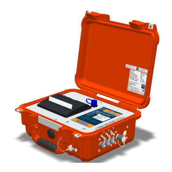
4 Ports Fig. 4.1: Product description Pressure input, 2 Measuring port, Power supply charging socket optional Pressure input, 1 Measuring port, On/off switch standard Pump controller input, Display light, (optional) on/off – brightness levels DAK2060 pressure relief kit control, 10. Thermal printer ESS calibration Temperature sensor input/measuring 11. -
Page 22: Accessories
Risk of injury/damage! Using non-approved accessories may cause damage and put persons at risk. Such use will void the warranty. The owner is then liable for any resulting damage. Only use genuine accessories or accessories approved by Union Instruments GmbH. Jul-2020... -
Page 23: Transport, Setup And Acceptance
5 Transport, setup and acceptance NOTE The PMS3000 pressure test kit comes ready to use. Make sure it is complete, intact and functioning properly before initial use! Notify Union Instruments GmbH or your distributor/retailer of any irregularities. Charge the battery with the included power supply for at least 6 hours before initial use (see Chapter 6). -
Page 24: Environmental Conditions
Transport, setup and acceptance 5.2 Environmental conditions NOTICE Observe environmental conditions for storage and setup. Make sure environmental conditions are met. Residual liquids may freeze at temperatures below 0 °C and cause damage. 5.2.1 Storage conditions Frozen water in the pressure test kit may cause damage. Completely drain the pressure test kit before storing and protect against frost. -
Page 25: Pressure Testing
Transport, setup and acceptance 5.4.1 Pressure testing NOTE • Accessories must be clean and free of residue. Contaminants may enter the pressure test kit and cause faulty measurements and/or damage. • Do not allow the input pressure for the measuring ports to exceed 1.3x the measurement range in bar. -
Page 26: Fig. 5.1: Interfaces
Transport, setup and acceptance Interfaces Fig. 5.1: Interfaces Designation USB (slave): access internal memory, transfer test sequences, read out test results (PDF, CSV) Electrical connections: communication with pump control, pressure relief kit, calibration ESS Power supply charging socket Battery charging Jul-2020... -
Page 27: Owner Safety Precautions
Leads and connected accessories may be under pressure. Risk of injury from uncontrolled opening of connections. • Tripping hazard from improperly placed leads. • Determine the measurement range of the sensor being used at test pressure; exceeding max. pressure may damage the sensor/PMS3000! Set up an organized work area. Jul-2020... - Page 28 Transport, setup and acceptance Jul-2020...
-
Page 29: Startup/Turning On
6 Startup/turning on NOTICE Charge the battery for min. 6 hours before initial startup. We recommend taking the following steps before beginning a test to ensure safe use and a complete test sequence: Steps Check whether the materials (stainless steel 1.4301, NBR) used in the kit are compatible with the test medium. -
Page 30: Fig. 6.1: Battery Status Display
Startup/turning on Fig. 6.1: Battery status display Designation Current information on battery, charge state, possible operating time (estimate depending on use, environment, accuracy ±20%), voltage Current data on battery use (battery counter), used for the internal calculation NOTE The status data of the battery provides an overview to allow estimates on the service life and capacity to be made. -
Page 31: Description Of The Interfaces/Operator Control Elements
7 Description of the interfaces/operator control elements NOTE This chapter only contains the elements for controlling the PMS3000 pressure test kit in measuring mode (normal mode). 7.1 Controls/features Fig. 7.1: Controls/features Designation Function/activity Display Show status, operate device, monitor test sequence... - Page 32 Description of the interfaces/operator control elements Jul-2020...
-
Page 33: Operation
8 Operation WARNING Risk of injury! Test pressure only if all connections and accessories are in proper working order and connected properly. Do not disconnect lines/connections that are under pressure. Release pressure completely before removal. Observe owner instructions and training. Jul-2020... -
Page 34: Description Of Display
Operation 8.1 Description of display 8.1.1 Turning on keypad Fig. 8.1: Turning on Turn on the pressure test kit by pressing key 3 “On/Off". Designation Function/activity Display Display and operate the kit with on-screen buttons Turn display on/off, set brightness in levels (35%, 50%, Display button 75%, 100%) Turn the device on/off, long-press (3 seconds) to... -
Page 35: Fig. 8.2: Operator Control Elements
Operation NOTE The display is resistive and can be operated with a stylus. Coarse soiling may scratch the display. We recommend touching the display directly with your fingers or a stylus for precise, simple operation. Fig. 8.2: Operator control elements Designation Function Status indicator... -
Page 36: Icons And Buttons
Operation The brightness can be set with the button to levels 35%, 50%, 75%, 100%. Display Press the button in quick succession – two times within one second – to change to the next brightness level. 8.2 Icons and buttons Buttons and icons are displayed in various colors depending on status and availability. -
Page 37: Status Led
Operation 8.3.2 Status LED The status LED next to the charging port indicates the following status information: Display Meaning Device is turned on, normal operation Flashing green Internal memory not detected Flashing red quickly Battery charging Flashing orange 8.4 Available screens NOTE The available screens and their function are described below. -
Page 38: Navigating Via Function Buttons
Operation 8.4.2 Navigating via function buttons Four function buttons for • selecting various display options Disabled displays gray • Enabled displays orange • • Active display blue Test sequence displays • current phase of the test sequence Active once test sequence is •... -
Page 39: Navigating Via Control Buttons
Operation 8.4.3 Navigating via control buttons Buttons at the bottom of the • screen for navigating menus and test sequences Button functions are • contextual Possible functions: Continue, • Back, Up, Down, Yes, No, Cancel. Entries made while navigating through the menu levels using are retained. -
Page 40: Input Via Virtual Keyboard
Operation 8.4.4 Input via virtual keyboard Virtual keyboard • for entering information (site info shown here) Delete input with delete • button <- Cancel, interrupts entry and • returns to the menu • Back, pages back to the last entry, new entries are not applied •... -
Page 41: Input With List Selection
Operation 8.4.5 Input with list selection Current selection dark at • center Navigate list using Up button • to go up and Down to go down • Cancel, interrupts entry and returns to the menu • Back, pages back to the last entry, new entries are not applied •... -
Page 42: Input Via Numeric Keypad
Operation 8.4.6 Input via numeric keypad NOTE Depending on the test sequence, the unit of measure used for numerical input is bar or mbar! • Virtual keyboard for entering information (test pressure shown here) • Enter decimal values with . Delete entries with backspace •... -
Page 43: Starting Test Sequence
Operation 8.4.7 Starting test sequence Test sequence begins after • confirming the pipe data Cancel, interrupts entry and • test sequence and returns to the menu No, pages to the start of the • data entry; previously entered data is retained and can be edited Yes, confirms entries and •... -
Page 44: Test Sequence Display
Operation 8.4.8 Test sequence display NOTE Test sequence starts, display shows progress and status. Green text indicates action required. Displays progress, no input • possible Test sequence phase • Current test data • Current parameters • • Waiting time and end time •... -
Page 45: Data
Operation 8.5 Data The PMS3000 saves data and information. The data can be downloaded via the USB port. Tests are saved as logs in PDF format; the data is saved as a CSV file. The test sequences with all entered data and any faults are saved as log files. -
Page 46: Printing With The Log Printer
• 8.5.4 Operating the log printer The printer is controlled and turned on/off by the PMS3000 software. The printer status LED lights green once the printer is turned on. Press and hold down button (1) on the printer to manually advance the paper. -
Page 47: Pdf Log File
PDF log files can be accessed via USB interface. To do this, the PMS3000 is to be connected to the USB interface of a PC using a USB connection cable and the USB menu item then selected in the main menu. - Page 48 Operation Jul-2020...
-
Page 49: Decommissioning/Turning Off
9 Decommissioning/turning off NOTICE To decommission the pressure test kit, first decommission connected system components according to their operating instructions. Risk of injury from pressurized leads and accessories! NOTE The following table contains steps for decommissioning the kit for extended periods. - Page 50 Decommissioning/turning off Jul-2020...
-
Page 51: Maintenance
Tests under DVGW G469 (A) and W400-2 Part 16 require annual calibration. 10.1 Calibration intervals Union Instruments recommends calibration yearly. Union offers a calibration service. 10.2 Replacing printer paper Open the cover by slightly lifting the panel with a finger and pulling upward. -
Page 52: Maintenance/Inspection
10.4 Maintenance/inspection DVGW rules and regulations require routine calibration. The PMS3000 displays a notice as soon as the calibration has expired. The notice must be confirmed with the Next button; the PMS3000 remains operational. A reminder is displayed six weeks prior to expiration of the calibration interval. -
Page 53: Troubleshooting
Furthermore, all fault messages are also recorded in the log folder in the corresponding log files. 11.3 Display without function If the battery of the PMS3000 was deep discharged, the battery must be charged for at least 10 minutes before the PMS3000 can be switched back on again. Jul-2020... -
Page 54: Firmware Update
Troubleshooting 11.4 Firmware update The firmware of the PMS3000 is continually developed further. Should a firmware update be necessary by the user due to stability reasons, this can be performed by the user. UNION provides firmware and information on installation. -
Page 55: Service
(see name plate) and any required spare parts/bills of materials numbers. The internal memory of the PMS3000 contains all data of the previously performed test sequences, see also 8.5! Union Instruments GmbH - Service Zeppelinstraße 42... - Page 56 Service Jul-2020...
-
Page 57: Related Documents
13 Related documents Pressure test kit declaration of conformity • Power supply declaration of conformity • • Accessory operating instructions If available Jul-2020... - Page 58 Related documents Jul-2020...
-
Page 59: Disposal
14 Disposal In case of decommissioning, you can return the device to Union Instruments GmbH. Suggestion: Have Union Instruments GmbH dispose of your pressure test kit. WARNING Risk of injury from electricity in the battery! NOTE Observe national regulations for disposal of machines and working materials. - Page 60 Disposal Jul-2020...
-
Page 61: Spare Parts
When replacing standard components, use only identical components from the original manufacturer! Use of parts from other manufacturers (due to an original part having been discontinued) requires the approval of Union Instruments GmbH. Spare parts can be ordered from Union Instruments GmbH: Chapter 12 Service. - Page 62 Spare parts Jul-2020...
-
Page 63: Appendix
Turning on ......... 34 Contact Virtual keyboard ......... 40 Service ..........55 Operator control elements ..... 31 Union Instruments GmbH ....17 Controls/features ........31 Personnel and qualification ....14 Ports ............21 Decommissioning ......49, 59 Pressure test system usage site .... 24 Display Pressure testing ........ -
Page 64: Figures
Appendix Figures Fig. 1.1: Pressure test kit dimensions................3 Fig. 1.2: Name plate (example) ..................6 Fig. 3.1: Designation Name plate ................19 Fig. 4.1: Product description ..................21 Fig. 5.1: Interfaces ...................... 26 Fig. 6.1: Battery status display ..................30 Fig. - Page 65 Jul-2020...
- Page 66 Appendix...
- Page 67 Jul-2020...
Need help?
Do you have a question about the PMS3000 and is the answer not in the manual?
Questions and answers