Union Instruments CWD2005 Original Operating Instructions
Combustion calorimeter
Hide thumbs
Also See for CWD2005:
- Operating instructions and safety notes (63 pages) ,
- Manual (123 pages)

Related Manuals for Union Instruments CWD2005


Summary of Contents for Union Instruments CWD2005
- Page 1 Original Operating Instructions Combustion Calorimeter CWD2005, CWD2005 Plus Apr-2016 V1.06...
- Page 2 UNION Instruments GmbH Zeppelinstraße 42 76185 Karlsruhe Germany +49 (0)721-680381-0 +49 (0)721-680381-33 support@union-instruments.com http://www.union-instruments.com © 2016 This documentation is protected by copyright. All rights, in particular the rights of translation, reprint, extraction of figures, radio transmission, and duplication by photomechanical or other means and of storage in data processing systems, in whole or in part, are reserved.
-
Page 3: Table Of Contents
Table of contents Table of contents Table of contents ......................... 3 Technical data ....................... 5 Dimensions ........................5 Device overview ......................6 Voltage supply ......................6 Interfaces ........................6 Display times of combustion value measurement ............7 Gas inputs ........................7 Calibration gas / Test gas ..................... - Page 4 Technical data 6.3.8 Electrical connection ....................37 6.3.9 Electrical interfaces ....................38 6.3.10 Connector assignment Input-Output IOexternal ............39 Commissioning after installation ................. 42 6.4.1 Removing/attaching transport securing devices............43 Documentation ......................44 Commissioning/Switching on ..................45 Description of the work stations/operator control elements ........47 Operation ........................
-
Page 5: Technical Data
Technical data Technical data 1.1 Dimensions Fig. 1.1: Housing dimensions Weight: approx. 54 kg... -
Page 6: Device Overview
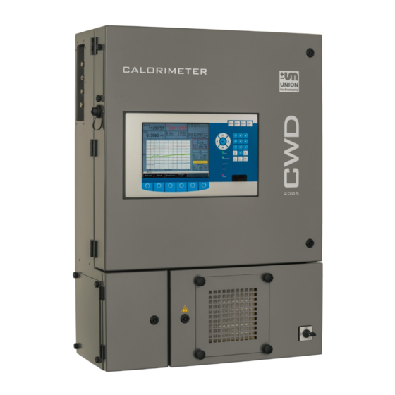
Technical data 1.2 Device overview Fig. 1.2: Markings and warning information 1. Warning information for electricity 2. Name plate 1.3 Voltage supply Voltage: 230 Volt or 115 Volt 50/60 Hz alternating current Power consumption: 185 VA max. Protection class: Degree of protection: IP50 1.4 Interfaces Interfaces:... -
Page 7: Display Times Of Combustion Value Measurement
1.5 Display times of combustion value measurement Dead time: 3 seconds 50% time: 7 seconds 90% time: CWD2005: 20 seconds, CWD2005 PLUS: 15 seconds 99% time: CWD2005: 60 seconds, CWD2005 PLUS: 55 seconds 1.6 Gas inputs Process gas: 1, optionally 2 for dual measuring ranges... -
Page 8: Process Gas
Gas connection inlet pressure: 20 - 40 mbar Gas consumption: 30 - 40 l/h (min. rel. density 0.50 with 0.55 mm nozzle) Measuring range [MJ/m] / Accuracy [± MBE] CWD device CWD2005 CWD2005 CWD2005 CWD2005 CWD2000 CWD2005 series PLUS Flare gas 0 –... -
Page 9: Environmental Conditions
1.10 Environmental conditions NOTICE When the combustion calorimeter is used outside of the environmental conditions, additional measures (air conditioning of the combustion calorimeter, etc.) must be agreed on with UNION Instruments GmbH! Installation location: Installation room required ( Chapter 4) Room temperature: 5 –... - Page 10 Technical data...
-
Page 11: Eu Declaration Of Conformity
Produktbezeichnung: Verbrennungskalorimeter Gerätegruppe: CWD2005 Product name: Calorimeter device group: CWD2005 konform sind mit den Anforderungen, die in der EU – Richtlinie festgelegt sind / are compliant with the require- ments as defined in the EU directive: 2014/30/EU Elektromagnetische Verträglichkeit 2014/30/EU... - Page 12 EU Declaration of Conformity...
-
Page 13: Safety Information
Safety information 3 Safety information 3.1 Warning information and symbols The operating instructions use the following nomenclature and symbols for espe- cially important information: DANGER For an immediate danger that can lead to serious physical injury or death! WARNING For a potentially dangerous situation that can lead to serious physical injury or death! NOTICE For a potentially dangerous situation that can lead to minor physical injury! This... -
Page 14: Principle, Intended Use
Additional equipment or accessory parts not installed, supplied, or made by UNION Instruments GmbH require manufacturer's approval by UNION Instru- ments GmbH! Any warranty is otherwise voided! The combustion calorimeter is a digitally controlled calorimeter. It measures ac- cording to the dry measurement principle. -
Page 15: Safety Information
Safety information 3.4 Safety information 3.4.1 General safety information WARNING Only operate the combustion calorimeter when all protective equipment is pre- sent and operational! Further safety information: Before the corresponding chapters! 3.4.2 Information on specific hazards DANGER • After installation, all gas-conveying parts must be checked for leak tightness according to national regulations. -
Page 16: Note On Explosion Protection
Safety information 3.4.3 Note on explosion protection NOTE The operation/installation of a UNION combustion calorimeter does not produce a hazardous area because combustible gas does not escape from the calorime- ter and form an explosive atmosphere. No combustible gas escapes from the UNION combustion calorimeter because: •... -
Page 17: Recurring Operator Training
Deviations from these operating instructions may occur due to further technical developments. If you desire additional information or if specific problems arise that are not covered in detail in this manual, you will receive information by contacting the following address: UNION Instruments GmbH Zeppelinstraße 42 76185 Karlsruhe Germany ... - Page 18 Safety information...
-
Page 19: Protective Equipment
Protective equipment 4 Protective equipment 4.1 Main switch Fig. 4.1: Main switch (example) 4.2 Safety switch The safety switch disconnects the ignition transformer from the voltage supply when the upper door is opened. Fig. 4.2: Figure Safety switch (example) -
Page 20: Thermal Cutoff
Protective equipment 4.3 Thermal cutoff NOTE The tripping temperature of the thermal cutoff is 72 °C. When tripped, the thermal cutoff disconnects the 24 V voltage supply of the sole- noid valves. 4.4 Solenoid valve In the event of malfunctions, the solenoid valves of the combustion calorimeter close automatically. -
Page 21: Markings And Warning Information
Protective equipment 4.7 Markings and warning information Fig. 4.3: Markings and warning information (example) Item Description Warning information: hot surface (internal) Warming information: electricity (external) Fig. 4.4: Warning information on electrical connection plate (example) - Page 22 Protective equipment...
-
Page 23: Description And Connections
Description and connections 5 Description and connections 5.1 Enclosure connections outside Fig. 5.1: Housing connections Item Description Cable glands for power supply Cable glands for signals Main switch Filter cover... - Page 24 Description and connections Item Description Door interlock (4 pieces) Display Flue exhaust Cover for analog signals (4 pieces) Fast Loop output (optional) Carrier gas input Calibration gas input (SV X14/3-4) Calibration gas input (SV X14/1-2) Process gas input (SV X11/1-2) Cover for interface connections (2 pieces) USB connection...
-
Page 25: Connections And Components Inside
Description and connections 5.2 Connections and components inside Fig. 5.2: Housing without doors, example Item Description Thermal cutoff (behind the exhaust gas pipe, on the rear wall) Thermal element Density measuring cell Precision pressure controller Electronic input and output signals Safety switch for ignition transformer Power supply distribution rail, example... -
Page 26: Accessories
Risk of injury/damage! The use of non-approved accessories may cause damage and endanger per- sons. Any warranty is voided in this case! The owner is then liable for damage that occurs! Only use genuine accessories or accessories approved by UNION Instruments GmbH. -
Page 27: Transport, Installation, And Acceptance
NOTE The combustion calorimeter is generally commissioned by UNION Instruments GmbH or correspondingly qualified service technicians. When it is not commissioned by UNION Instruments GmbH (e.g., internal transport/resale), the suitable procedure must be agreed with UNION Instru- ments GmbH ( Chapter 13 Service). -
Page 28: Environmental Conditions
6.2 Environmental conditions NOTICE Comply with environmental conditions for storage and installation! Contact UNION Instruments GmbH if the combustion calorimeter is stored for longer than 3 months or must be operated or stored outside the prescribed environ- mental conditions! 6.2.1 Storage conditions NOTE •... -
Page 29: Installing And Connecting
Transport, installation, and acceptance 6.3 Installing and connecting 6.3.1 Installation location The installation location of the combustion calorimeter must meet the following conditions: • Clean room that may be used only for purposes of gas analysis and measure- ments. • At least 50 cm working space on the left side •... -
Page 30: Room Ventilation
Transport, installation, and acceptance 6.3.2 Room ventilation WARNING Risk of injury due to temperature of exhaust gas/housing! The exhaust gas temperature is between 8 - 20 °C above the housing tempera- ture! Use personal safety equipment to prevent burns! NOTE In the case of unfavorable circulation/installation conditions, appropriate deflect- ing sheets must be provided that prevent fresh air from flowing directly onto the combustion calorimeter. -
Page 31: Wall Mounting
Transport, installation, and acceptance 6.3.3 Wall mounting WARNING Risk of injury due to the weight of the device! For weight, see technical data! Specify measures to prevent the device from falling down and use suitable hoist- ing devices! NOTE Adequate distance must be provided between the side wall of the installation lo- cation and the combustion calorimeter for service and maintenance. -
Page 32: Fig. 6.1: Wall Mounting
Transport, installation, and acceptance Fig. 6.1: Wall mounting Fig. 6.2: Dimensions wall mounting... -
Page 33: Process Gas
Transport, installation, and acceptance 6.3.4 Process gas WARNING Gas connections may only be installed by qualified personnel! Exhaust gases must be discharged by the owner to a safe environment! NOTE • Connection parts must be clean and free of residues. Contaminants may reach inside the combustion calorimeter and may cause false measurements and/or damage. -
Page 34: Carrier Gas Supply
Transport, installation, and acceptance 6.3.5 Carrier gas supply NOTE • Combustion calorimeters can be subsequently converted to a carrier gas supply. Contact the manufacturer regarding this. • For process gases that do not have stable combustion, a carrier gas can be added. -
Page 35: Calibration Gas
Transport, installation, and acceptance 6.3.6 Calibration gas WARNING Gas connections may only be installed by qualified personnel! If a pressure reducer is not installed, escaping calibration gas must be dis- charged by the owner to a safe environment! NOTE • Connection parts must be clean and free of residues. -
Page 36: Flue Gas
Transport, installation, and acceptance 6.3.7 Flue gas WARNING Risk of serious injury from escaping flue gases! • Flue gases must be discharged to the outside! • For flue gases containing CO, H and H S, adequate room ventilation must be ensured. NOTE Flue gases/residual heat must be discharged to the outside protected from air draft and without interruption through a vent. -
Page 37: Electrical Connection
Transport, installation, and acceptance 6.3.8 Electrical connection DANGER Danger of electric shock! Changes to the electrical equipment of the combustion calorimeter may be car- ried out only be skilled electricians in accordance with electrotechnical rules. Parts of the open combustion calorimeter marked with the adjacent symbol may still carry voltage even when the main switch is switched off! If required, discon- nect the combustion calorimeter from the supply network. -
Page 38: Electrical Interfaces
Transport, installation, and acceptance WARNING After the line voltage is switched off, the device capacitors still carry voltage for up to 5 minutes! This time must be allowed to elapse before starting work on the high voltage electrical system. NOTE •... -
Page 39: Connector Assignment Input-Output Ioexternal
Transport, installation, and acceptance 6.3.10 Connector assignment Input-Output IOexternal Fig. 6.5: Connector assignment Input-Output IO type 06 WARNING Do not connect to line voltage! Only operate outputs (relay, analog, digital) and inputs with safety extra-low volt- age! Only connect serial interface – RS232 – to an electrically safe device! - Page 40 Transport, installation, and acceptance Relay outputs Connector X14 Digital output Pin/Connector X14 Function Status display Common Process Normally open Normally closed Common Maintenance Normally open Normally closed Common Filter change Normally open Normally closed 10 Common Fault 11 Normally open 12 Normally closed 13 Common Function, if applica-...
- Page 41 Transport, installation, and acceptance Digital control inputs Connector X3 Control inputs Pin/Connector Function Status display diode Start measurement D 25 Start measurement Start calibration D 24 Start calibration Function, if applica- D 23 optionally assigned Function, if applica- D 22 optionally assigned Function, if applica- D 21...
-
Page 42: Commissioning After Installation
Transport, installation, and acceptance 6.4 Commissioning after installation WARNING Endangerment of people and equipment when the combustion calorimeter is commissioned by non-instructed personnel! Allow only instructed/trained service technicians to carry out commissioning! -
Page 43: Removing/Attaching Transport Securing Devices
Transport, installation, and acceptance 6.4.1 Removing/attaching transport securing devices NOTE Before commissioning/transport of the combustion calorimeter, it must be en- sured that all transport securing devices are removed/attached. The following transport securing devices must be removed/attached within the combustion calorimeter: Fig. -
Page 44: Documentation
• Loosen the eyebolt. • Density measuring cell must swing free. Proceed in reverse order to reattach the transport securing device. 6.5 Documentation NOTE UNION Instruments GmbH recommends keeping a maintenance manual and doc- umenting all work and tests. -
Page 45: Commissioning/Switching On
Commissioning/Switching on 7 Commissioning/Switching on NOTICE In order to establish start readiness, also establish the start readiness of linked system components according to their operating instructions! NOTE For initial commissioning or before an extended operating shutdown, back up the device configuration. Have the backup made be service technicians or in response to a special service instruction. - Page 46 Commissioning/Switching on Com- Switch- Steps mis- ingon sioning Check whether the transport securing device has been removed. The density cell must be able to swing freely at the springs. Ensure voltage. Ensure that the door is closed (safety switch). Switch on the main switch. Establish start readiness of linked system components.
-
Page 47: Description Of The Work Stations/Operator Control Elements
Description of the work stations/operator control elements 8 Description of the work stations/operator control elements NOTE This chapter contains only elements for operation of the combustion calorimeter by the normal operator. Fig. 8.1: Work stations Item Description Function/Activity Display Displaying status and operation Main switch Switching the device On/Off... - Page 48 Description of the work stations/operator control elements...
-
Page 49: Operation
Operation 9 Operation WARNING Risk of injury! Only operate the combustion calorimeter when all lines are installed and have been checked for leak tightness in accordance with country-specific regulations. 9.1 Operation of membrane keyboard/Description of display The software controller is operated using a membrane keyboard. The buttons shown can be selected by pressing them. - Page 50 Operation Item Description Function Numeric display Output of current measured values Display field Information field Arrows/Return Arrow keys enable movement to an input field. The Return key confirms the entered value. Menu Menu key returns you to the main menu from any other menu level.
-
Page 51: Basic Operation
Operation 9.2 Basic operation The keys described in the following are used for operation of the combustion calo- rimeter on the part of the software. Symbol Function Back: • Causes the menu to jump to the next higher menu level all the way back to the main menu. -
Page 52: General Information
Operation 9.4 General information Fig. 9.2: General information Display Information (example values) V 4.39R09 Version number of the software 04.02.2015 10:05:09 Current date / time Methane: 95.01 Vol% Volume share of methane mV=24.56 mV signal of the thermal battery V=1.071 Voltage signal of the density measuring cell T1=29.04/0.24 Inlet temperature into the thermal body / heating of the... -
Page 53: Menu Structure
Operation 9.5 Menu structure Main menu ......................... 54 9.6.1 Main menu - Options ....................55 Main menu - Options - I/O ..................56 Main menu - Options - I/O - Analog outputs ............57 Main menu - Options - I/O - Digital outputs ............58 Main menu - Options - I/O - mA display ............ -
Page 54: Main Menu
Operation 9.6 Main menu The main menu is the standard display during active operation. The following menus are accessed from the main menu: • Options • Trend • Eventlist • Device info... -
Page 55: Main Menu - Options
Operation 9.6.1 Main menu - Options Configuration possibility for the following parameters: • Analog outputs • Digital (relay) outputs • mA display • Digital inputs • Display Calibration Configuration possibility for the following parameters: • Configuration of calibration gas • Automatic calibration •... -
Page 56: Main Menu - Options - I/O
Operation Main menu - Options - I/O Options for configuration for the following parameters: • Analog outputs • Relay outputs • Disp. mA • Digital inputs • Display... -
Page 57: Main Menu - Options - I/O - Analog Outputs
Operation Main menu - Options - I/O - Analog outputs The mA signals are configured in this menu. Signal (list field) Wobbe-index, density, heating value, Type (list field) 4 – 20 mA Unit (list field) kcal/m³, relative MB from MB to value fields for numeric input The following must be observed for this: Units:... -
Page 58: Main Menu - Options - I/O - Digital Outputs
Operation Main menu - Options - I/O - Digital outputs Digital signals (relay outputs, floating change-over contacts) are configured in this menu. The following must be observed for this: Zero position: The zero position of the digital outputs can be freely selected: low/high. Process: The process gas solenoid valve is open and the flame is burning. - Page 59 Operation Fault: Device is no longer usable because • Air differential pressure is too low (< 3.5 mbar) • Sensor break (PT100, thermoelectric battery, temperature at burner is too high) • Gas pressure is too low Operation: The flame is burning. Thermoelectric voltage of process or calibration gas is greater than the ignition threshold.
-
Page 60: Main Menu - Options - I/O - Ma Display
Operation Main menu - Options - I/O - mA display The mA values for the currently active outputs are displayed in this menu. With the Disp. mA key, all channels can be displayed one after the other. The value can be obtained from the "General information"... -
Page 61: Main Menu - Options - I/O - Digital Inputs
Various digital signals are configured in this menu. The following must be observed for this: The pin assignment is preassigned. Chapter 6.3.10 Connector assignment Input-Output IOexternal! Signals Zero position Contact CWD2005 open Calibration starts high closed No calibration Start calibration open... -
Page 62: Main Menu - Options - I/O - Display
Operation Main menu - Options - I/O - Display The display of measured values is configured in this display. A signal and a unit is assigned to each of the 4 display windows. -
Page 63: Main Menu - Options - Calibration
Operation Main menu - Options - Calibration Calibration values are configured in this menu. -
Page 64: Main Menu - Options - Calibration - Configuration Of Calibration Gas
Operation Main menu - Options - Calibration - Configuration of calibration gas The calibration gas is configured in this menu. The following must be observed for this: The calibration gas is input as a Wobbe index (Wobbe i and Wobbe s) and as a relative density. -
Page 65: Main Menu - Options - Calibration - Automatic Calibration
Operation Main menu - Options - Calibration - Automatic calibration The automatic calibration is configured in this menu. The following must be observed for this: Input: Day is a list field (Su, Mo, Tu, We, etc.), Time and Cycle are value fields. Duration of calibration: Depending on the device type, the calibration duration is 10 - 20 min. -
Page 66: Main Menu - Options - Calibration - Automatic Calibration 2
Operation Main menu - Options - Calibration - Automatic calibration 2 The automatic calibration that is defined by a situation is configured in this menu. Criterion 1: Automatic calibration after restart. Criterion 2: Automatic calibration at a defined change in ambient temperature compared to the last calibration. -
Page 67: Main Menu - Options - Calibration - Calibration Limits
Operation Main menu - Options - Calibration - Calibration limits The calibration tolerances are set and the deviations from the base calibration are displayed in this menu. If the calibration values exceed the defined tolerances, this is indicated as a calibration deviation for digital outputs. -
Page 68: Main Menu - Options - System
Operation Main menu - Options - System The basic configurations of the device, such as ignition, time of day, language, and code key, are specified in this menu. -
Page 69: Main Menu - Options - System - General
Operation Main menu - Options - System - General The "Change signals after holding" command causes a smooth transition after cal- ibration or removal of the signal holding state. A sudden rise or fall of the measured value in the analog output signal is avoided. The continuous transition is specified in seconds. - Page 70 Operation Operation delay: The "Operation" relay output is activated only after the delay time elapses. Minimum internal pressure: When the minimum internal pressure is fallen below, the device goes to STOP state, default value is 8 mbar. Internal pressure warning threshold: Below the warning threshold, insufficient gas is signaled for internal pressure and Service.
-
Page 71: Main Menu - Options - System - Ignition
Operation Main menu - Options - System - Ignition NOTE The combustion calorimeter can only be ignited when the door is closed. The ignition monitoring is configured in this menu. The following must be observed for this: Single ignition or interval ignition must be chosen. Single ignition: After device start and the flushing time period (10 s), the ignition starts for the max- imum set ignition duration. -
Page 72: Main Menu - Options - System - Load Factory Settings
Operation Main menu - Options - System - Load factory settings The factory settings are loaded with this key. Main menu - Options - System - CSV Export Three files are exported as an ASCI file with this key: 30 min at 1-second intervals, 3 hours at 10 second intervals, and 5 days at 1-minute intervals. -
Page 73: Main Menu - Options - System - Settings
Operation Main menu - Options - System - Settings Main menu - Options - System - Settings – Date / Time The date and time are set in this menu. Increments selected numbers Decrements selected numbers Moves one field left Moves one field right... -
Page 74: Main Menu - Options - System - Settings - Language
Operation Main menu - Options - System - Settings - Language The Language menu item contains 10 submenus for inserting, copying, and cor- recting various languages, even those that have to be represented by bitmaps (e.g., Chinese). Download languages onto a memory stick, correct them, and then re-import them to the combustion calorimeter. -
Page 75: Main Menu - Options - System - Settings - Password
Operation Main menu - Options - System - Settings - Password The password is changed in this menu. The following must be observed for this: Factory password: The combustion calorimeter is delivered with factory password 0. This can be changed, if necessary. Unlock time: This time specifies when the system will be locked and the password must be re- entered. -
Page 76: Main Menu - Options - System - Settings - Change Color
Operation Main menu - Options - System - Settings - Change color The display colors can be changed here. -
Page 77: Main Menu - Options - System - Settings - Hardware 1
Operation Main menu - Options - System - Settings - Hardware 1 NOTE Only change this menu in consultation with the manufacturer. The parameters for a multi-range measuring device are configured in this menu. The screen shows all possible configurations. Range No. - Page 78 Operation Range cfg. is a binary coding for the measurement conditions while a measuring range switchover is in process. measuring range not loaded nozzle set 2 or nozzle set 1 air nozzle on or off flammable carrier gas on or off not flammable carrier gas (oxygen) on or off flammable carrier gas that does not burn by itself on or off The number 6 indicates that the measuring range is operated with nozzle set 1 and...
-
Page 79: Main Menu - Options - Service
Operation Main menu - Options - Service NOTE Only change this menu in consultation with the manufacturer. The menu is password-protected. Setting for Service only. -
Page 80: Main Menu - Trend
Operation 9.6.2 Main menu - Trend The graphics are configured in this menu. The following must be observed for this: Up to three different curves in various colors can be displayed. Selection: A selection can be made from the following parameters: •... -
Page 81: Main Menu - Graphic - Select Time
Operation Main menu - Graphic - Select time The diagram can be optimally designed. The increments for increasing and reduc- ing are programmed in order to obtain a resolution. The diagram is subdivided into 10 segments on the x-axis. The segment time and the total displayed time can be set as follows: Increase segment time Reduce segment time... -
Page 82: Main Menu - Graphic - Select Value
Operation Main menu - Graphic - Select value • Values for the curves can be set in this menu. The curves can be viewed as follows: Ref y-value linearly to y-axis Ref y-value linearly from y-axis dy value compressed y-axis dy value stretched y-axis... -
Page 83: Main Menu - Graphic - Select Signal
Operation Main menu - Graphic - Select signal • Signals for the curves can be selected in this menu. • Examples of signals: Wobbe i Heating value mVSA Frequency T amb Wobbe s Combustion p Wobbe T in value Main menu - Graphic - Select unit •... -
Page 84: Main Menu - Graphic - Select Curve
Operation Main menu - Graphic - Select curve Individual curves can be selected in this menu in order to change parameters. -
Page 85: Main Menu - Event List
Operation 9.6.3 Main menu - Event list NOTE The event list stores all events that are of interest for operation and service of the device. A total of 1000 events can be stored. Show startup Selection of the different events Show calibration Selection of the different events Show all... -
Page 86: Main Menu - Device Information
Operation 9.6.4 Main menu - Device information NOTE The values shown are very important for remote diagnostics when errors occur and can be loaded onto the memory stick and sent to the manufacturer by email, refer to CSV Export, Index. Device data: •... - Page 87 Operation...
- Page 88 Operation...
-
Page 89: Decommissioning / Switching Off
Decommissioning / Switching off 10 Decommissioning / Switching off WARNING Endangerment of people and equipment when the combustion calorimeter is de- commissioned by non-instructed personnel! Allow only instructed/trained service technicians to carry out decommissioning! NOTICE In order to decommission the combustion calorimeter, also decommission the linked system components according to their operating instructions! NOTE The following table contains steps for decommissioning for an extended down-... - Page 90 Decommissioning / Switching off...
-
Page 91: Maintenance
Maintenance 11 Maintenance The quality of measurements by the combustion calorimeter can only be guaran- teed when the maintenance intervals are adhered to. 11.1 Preparations Supply lines of linked system components can be closed for maintenance pur- poses. These must be reopened after the device is put back into service. DANGER Risk of serious injury from electricity! •... -
Page 92: Maintenance Work/Inspection
Maintenance 11.2 Maintenance work/Inspection NOTE Maintenance work must be performed according to the inspection and mainte- nance schedule! The nature and amount of wear depends greatly on the individ- ual use and operating conditions. All specified intervals are therefore guide val- ues. - Page 93 Maintenance Interval Check (recommended) After commissioning Check and, if necessary, update the firmware version. As required Store the current configuration As required Semi-annual check Check air filter for contamination/clogging. Every 6 months Perform calibration (at shorter intervals depending on accuracy re- As required quirements) Check tube connection to the density measuring cell/sensors for...
- Page 94 Maintenance...
-
Page 95: Troubleshooting
Troubleshooting 12 Troubleshooting WARNING Risk of serious injury from electricity and escaping gases! • Before carrying out maintenance work on the combustion calorimeter and whenever necessary, also bring the the linked system components to a standstill. • Switch off the main switch, and disconnect the device from the voltage sup- ply if necessary, and take steps to prevent the main switch from being switched on again and the voltage supply from being reconnected! •... -
Page 96: Preparations For Troubleshooting
Troubleshooting 12.1 Preparations for troubleshooting Supply lines of linked system components can be closed for maintenance pur- poses. These must be reopened after the device is put back into service. NOTE Event list: The software keeps an event list with up to 1000 events in chronological order (specification of date). -
Page 97: Changing/Replacing Fuses
Troubleshooting 12.2 Changing/replacing fuses Only skilled electricians or service technicians are permitted to replace fuses. Only replace with fuse types specified by UNION. 12.3 Unstable measured value • The inlet pressure controller cannot maintain a constant inlet pressure. The process pressure (blast furnace gas) is too high. A pressure booster pump must be installed. -
Page 98: Error/Status Messages
Troubleshooting 12.4.2 Error/status messages Filter change • Filter change (air filter) • The frequency of the frequency converter is > than the set threshold value. Int. pressure • Alarm in the event of inadequate process gas or calibration gas • Adjustable threshold;... - Page 99 Troubleshooting Calibration • Flame is burning, solenoid valve for calibration gas is open • Calibration is active, no mA signals are output, these are "on hold", the last current value is retained.
- Page 100 Troubleshooting...
-
Page 101: Service
Service 13 Service NOTE UNION Instruments GmbH is available to answer any questions. In case of orders or technical questions, please provide your customer number, phone number where you can be reached, the combustion calorimeter type and number (see name plate), and required spare parts/bills of material numbers, if applicable. - Page 102 Service...
-
Page 103: Disposal
Disposal 14 Disposal In case of decommissioning, a return of the device to UNION Instruments GmbH is possible. Suggestion: Have UNION Instruments GmbH dispose of your combustion calorim- eter. WARNING Risk of injury from electricity and, if applicable, gases in the combustion calo-... - Page 104 Disposal...
-
Page 105: Spare Parts
When standard components are replaced, use only identical components of the original manufacturer! In the event that components are discontinued or compo- nents of other manufacturers are used, this requires manufacturer's approval by UNION Instruments GmbH! Spare parts can be ordered from UNION Instruments GmbH: Chapter 11 Service. ... - Page 106 Spare parts...
-
Page 107: Appendix
Zustand Filter- BYTE 1 = Filterwechsel am CWD benötigt wechsel BYTE Reserve Table 1: Data structure Profibus For more information about communication with Profibus and the UNION calorim- eter see Service UNION Instruments GmbH, Kapitel 11 Service. CWD = Calorimeter... -
Page 108: Data Struture Serial Interface Rs 232 (Option)
Data struture serial interface RS 232 (option) Data struture serial interface RS 232 (option) With the optional serial interface (RS 232) data can be transmitted. Parameters are selected in the "I / O Analog outputs". The interface has to be activated in the menu service. -
Page 109: Index
Connecting ..........29 Connections ........... 23 Operation ..........49 Contact Operator control elements ..... 47 Service ..........101 UNION Instruments GmbH ....17 Personnel and qualification ....14 CSV Export ..........72 Profibus Data structure ........107 Decommissioning ......89, 103 Protective equipment ...... -
Page 110: List Of Figures
List of figures List of figures Fig. 1.1: Housing dimensions ..................5 Fig. 1.2: Markings and warning information ..............6 Fig. 4.1: Main switch (example) ................... 19 Fig. 4.2: Figure Safety switch (example) ..............19 Fig. 4.3: Markings and warning information (example) ..........21 Fig.
Need help?
Do you have a question about the CWD2005 and is the answer not in the manual?
Questions and answers