
Related Manuals for Union Instruments CWD2000 EX


Summary of Contents for Union Instruments CWD2000 EX
- Page 1 Original operating instructions Combustion calorimeter CWD2000 EX April-2015 V1.04...
- Page 2 Union Instruments GmbH Zeppelinstraße 42 76185 Karlsruhe Germany +49 (0)721-680381-0 +49 (0)721-680381-33 support@union-instruments.com http://www.union-instruments.com © 2015 This documentation is copyrighted. The engendered rights are retained, in particular the rights to translation, reprinting, taking pictures, radio transmission, reproduction by photomechanical or similar methods and storage in data processing systems, including excerpts.
-
Page 3: Table Of Contents
Table of contents Table of contents Technical data ....................... 5 Dimensions ........................5 Ex marking according to EC type examination .............. 7 Device specifications ....................7 Interfaces ........................7 Display times of calorific value measurement0F ............7 Calibration gas ......................7 Process gas ........................ - Page 4 Table of contents 6.3.10 Removing / attaching the transport safeguard ............36 Documentation ......................37 Commissioning/start-up ..................... 39 Description of the workplaces / operating elements ..........41 Operation ........................43 Starting – Switching on ....................43 Operation of film keyboard/ description of display ............43 Basics on operation ....................
-
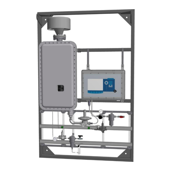
Page 5: Technical Data
Technical data Technical data 1.1 Dimensions Fig. 1.1: Dimensions of rack, System overview (exemplary) - Page 6 Table of contents...
-
Page 7: Ex Marking According To Ec Type Examination
Technical data 1.2 Ex marking according to EC type examination Ex marking : II 2G Ex d IIA T3 Gb EC type examination : BVS 04 ATEX E 018 X -20°C ≤ T ≤ + 45°C Ambient temperature: 1.3 Device specifications Parameter: calorific value Other parameters:... -
Page 8: Linearity And Measuring Range
Table of contents Air requirement Approx. 30 m³ per hour (air in installation room: contains max. 50 ppm combustible components) 1.8 Linearity and measuring range The measuring ranges cannot be used from 0% to 100%. The range depends on the gas composition. Typical for a measuring range are 45 – 100 %. The hydrogen content in the gas increases the measuring range span. - Page 9 Technical data...
-
Page 11: Ec Declaration Of Conformity
EC declaration of conformity 2 EC declaration of conformity Further information: enclosed documentation! - Page 12 Table of contents...
-
Page 13: Safety Instructions
Safety instructions 3 Safety instructions 3.1 Warnings and symbols In the operating instructions, the following names and symbols are used to denote particularly important information: DANGER The calorimeter is approved in accordance with the EC type approval for use in hazardous areas. -
Page 14: Principle, Correct Use
Additional equipment or accessories that are not installed, delivered or manufactured by UNION Instruments GmbH require the approval of UNION Instruments GmbH as the manufacturer! Otherwise the guarantee expires. The combustion calorimeter is a digitally controlled calorimeter. It measures using the dry measurement principle. -
Page 15: Safety Instructions
Safety instructions 3.4 Safety instructions 3.4.1 General safety notes WARNING The combustion calorimeter may only be operated when all of the protective equipment is available and operable. Additional safety notes: before the corresponding chapters! 3.4.2 Notes on specific hazards DANGER ... -
Page 16: Regular Operator Training
Table of contents 3.5.1 Regular operator training NOTE Country-specific regulations about regular user training by the operator must be observed, in particular training on handling explosive areas, gases, and electrical equipment. 3.5.2 Workplace hazard analysis NOTE Depending on national regulations and possible independent of the CE marking of this combustion calorimeter, the operator has to create a workplace risk analysis and to specify the personal protective equipment for the different phases of operation. -
Page 17: Safety Devices
Safety devices 4 Safety devices The calorimeter is a combination of an explosion proof box (analyzer) and pressurized box with an air heater and PLC. The connection between the boxes is the Instrument air tube. In the case of loosing the instrument air pressure a non- return valve prevent a flow back to the heating system. -
Page 18: Solenoid Valve
Table of contents 4.6 Solenoid valve In case of faults, the solenoid valves of the combustion calorimeter close automatically. The combustion calorimeter then needs to be restarted. -
Page 19: Markings And Warnings
Safety devices Markings and warnings Fig. Markings and warnings (exemplary) - Page 20 Table of contents...
- Page 21 Safety devices...
- Page 22 Table of contents Exemplary image The identification plate is created after acceptance and approval by the manufacturer of the purge control unit (Gönnheimer) and added by Union Instruments.
-
Page 23: Description And Connections
Description and connections 5 Description and connections NOTE Up to 2 process gas lines can be connected. Fig. Housing connections Item designation Cable gland signals to calorimeter Cable gland power supply Control panel Cable gland signals customer Cable gland power supply heater Instrument air in Instrument air out USB port... -
Page 24: Fig. 5.2: Housing Without Doors
Table of contents Fig. 5.2: Housing without doors Item designation Thermal fuse Pre- pressure regulator (Set: 16 mbar) Density measuring cell Nozzel differential pressure density cell (dp: 4 mbar) Thermal body Pressure switch air pressure 4 mbar Precision pressure controller (Set: 4 mbar) Nozzel air (Ø... -
Page 25: Accessories
Description and connections 5.1 Accessories WARNING Risk of injury/defective! Use of non-approved accessories can cause defects and be hazardous. This will render the warranty null and void! The operator is liable for incurring damage! Observe to EX type examination! Only use original accessories or accessories that have been approved by Union Instruments GmbH. -
Page 26: Transport, Installation And Acceptance
The combustion calorimeter is generally put into service by Union Instruments GmbH or a service technician with appropriate qualification. If it is not transported, set up and started up by Union Instruments GmbH (for example in-house transportation and resale), coordinate the appropriate procedure with Union Instruments GmbH (... -
Page 27: Specific Gravity Sensor
Transport, installation and acceptance 6.1.1 Specific Gravity Sensor Remove the transport tie wraps and transport screws from the specific gravity cell. The body of the cell must hang free on the springs and not come into contact with the sides of the bracket. The screw should be removed and stored and the following diagram illustrates the process. -
Page 28: Gas Pressure Regulator
Table of contents 6.1.2 Gas pressure regulator Remove the transport packing from the gas pressure regulator. Polystyrene foam is located beneath the removable regulator cover and must be removed before use. Fig. 6.4: Gas pressure regulator 6.1.3 Flue Stack The flue stack has to be mounted. The flue stack is delivered as loose part and attached at the rack. -
Page 29: Ambient Conditions
Transport, installation and acceptance 6.2 Ambient conditions ATTENTION Observe the ambient conditions during storage and set up! Contact Union Instruments GmbH if the combustion calorimeter has been stored for more than three months or needs to be operated or stored under ambient conditions other than those specified! 6.2.1 Storage conditions NOTE... -
Page 30: Installing And Connecting
Table of contents 6.3 Installing and connecting 6.3.1 Setup site The installation location of the combustion calorimeter must meet the following requirements: space of at least 50 cm to the front and below entrance and exit as air locks ... -
Page 31: Process Gas
Transport, installation and acceptance 6.3.4 Process gas DANGER The connecting parts need to be clean and free of residue. Impurities can enter the combustion calorimeter and cause incorrect measurements and/or damage. Gas inlet pressure depending on the gas between 20 and 40 mbar ... -
Page 32: Calibration Gas
Table of contents 6.3.5 Calibration gas WARNING Only qualified trained staff must install the gas connections! If no pressure reducers are installed, the operator must make sure that escaping calibration gas is emitted to a safe environment! NOTE The connecting parts need to be clean and free of residue. Impurities can enter the combustion calorimeter and cause incorrect measurements and/or damage. -
Page 33: Flue Gas
Transport, installation and acceptance 6.3.6 Flue gas WARNING Serious risk of injury from escaping flue gas. Flue gas must be emitted to the open air! For flue gases with the components CO, H and H S ensure sufficient room ventilation. -
Page 34: Opening, Closing Of Cover Plate
Table of contents 6.3.7 Opening, closing of cover plate DANGER Loss of explosion protection! Danger of explosion in hazardous areas by open or not properly closed device! Before closing the door of the EX-d box, the intactness and cleanness of the machined flange surfaces and the gasket is to check in any case. -
Page 35: Groundig Of The Ex-D Box
Transport, installation and acceptance 6.3.9 Groundig of the EX-d box NOTE The enclosure must be earthed separately in each case. The port is located on the outside, in the lower-right corner. The Connector kit, is attached to the earth connector on delivery. Fig. -
Page 36: Removing / Attaching The Transport Safeguard
Table of contents 6.3.10 Removing / attaching the transport safeguard NOTE Before commissioning/transport of the combustion calorimeter, make sure that all transport safeguards are removed/attached. The following transport safeguards must be removed/attached in the combustion calorimeter: Fig. 6.7: Transport safeguards (example) Item Component Type of safeguard... -
Page 37: Documentation
Unscrew the eyebolt. The density measuring cell must swing freely. To re-attach the transport safeguard, proceed in reverse order. 6.4 Documentation NOTE Union Instruments GmbH recommends keeping a maintenance manual and documenting all jobs and tests. - Page 38 Table of contents...
-
Page 39: Commissioning/Start-Up
By an improper assembly the device can be damaged, destroyed or be affected in the functioning. Improper Assembly inevitably leads to the loss of explosion protection. Work on the system, must be carried out by trained and authorised staff or by the specialists of UNION Instruments service team. - Page 40 Table of contents Turning Steps Startup Check if the transport safeguard of the density measuring cell has been removed. The density measuring cell must be able to swing freely at the springs. Check if the transport safeguard of the gas pressure controller has been removed.
-
Page 41: Description Of The Workplaces / Operating Elements
Description of the workplaces / operating elements 8 Description of the workplaces / operating elements NOTE This chapter only discusses the elements used by normal operators to operate the combustion calorimeter. Fig. Workplaces (exemplary) Item designation Function / activity Display Status display and operation. - Page 42 Table of contents...
-
Page 43: Operation
Operation 9 Operation WARNING Danger of injury! Only use the combustion calorimeter when all lines have been installed and checked for leaks according to national regulations. 9.1 Starting – Switching on After closing the lid, wait for 10 minutes. The overpressure will be built up. Then the combustion calorimeter starts automatically. -
Page 44: Fig. 9.1: Operating Elements/Layout Of Display
Table of contents Fig. 9.1: Operating elements/layout of display... - Page 45 Operation designation Function Item Numeric display Output of current measurement values after reaching the operating mode. Display field Information field, start screen. Position buttons Position buttons move the cursor in a current input field to the input position. With the return button you confirm the entered value.
-
Page 46: Basics On Operation
Table of contents 9.3 Basics on operation The buttons described in the following serve for operation via the software of the combustion calorimeter. Symbol Function Symbol "Back" in the menu buttons: Cause a jump to one menu level up at a time until the main menu is reached. -
Page 47: General Information On The Start Screen
Operation 9.5 General information on the start screen Fig. 9.2: Information field, start screen. Display Information (example values) V 4.39R09 Version number of the software 04.02.2015 10:05:09 Current date / time Methane: 95.01 Vol% Volume share of methane mV=24.56 mV signal of the thermal battery V=1.071 Voltage signal of the density measuring cell T1=29.04/0.24... -
Page 48: Menu Structure
Table of contents 9.6 Menu structure... -
Page 49: Main Menu
Operation 9.7 Main menu The main menu is the standard display in running operation. From the main menu you can access the following sub-menus: Options Trend Eventslist Device info... -
Page 50: Main Menu - Options
Table of contents 9.7.1 Main menu - Options NOTE The free part of the info field is filled with important information, depending on the menu selection, which refers to current activities, e.g. filter change, temperature too high. Option to configure the following parameters: ... - Page 51 Operation Main menu - Options - I/O Options for configuration for the following parameters: Analog outputs Relay outputs Disp. mA Digital inputs Display...
- Page 52 Table of contents Main menu - Options - I/O - Analog outputs Signal (list field) Wobbe index, density, heating value 4 – 20 mA Type (list field) Unit (list field) kcal/m³, relative MB from MB to value fields for numeric input Units: xxx/m ³...
- Page 53 Operation Main menu - Options - I/O - Digital outputs The digital output can e.g. comprise signals in combination with limit values or operation messages. Example: The Wobbe signal in MJ/m³ has an alarm value at 47,000 and 50,000 MJ. The zero position is high.
- Page 54 Table of contents Main menu - Options - I/O - mA display In the menu item Disp. mA you can display the mA values for all 7 outputs. The display is located on the upper right below the date. With the button Disp. mA you can show all channels one after the other.
- Page 55 Operation Main menu - Options - I/O - Digital inputs Signal and zero position are list fields. These inputs can start a calibration or switch a holding amplifier on or off. The inputs are queried once per second. i.e. a change must be pending for at least one second in order to be detected by the system.
- Page 56 Table of contents Main menu - Options - I/O - display The numeric display in the display can be selected arbitrarily. Any pre-set value can be entered in the display on the upper left. Size and unit are list fields, they determine the numeric display on the device's screen.
- Page 57 Operation Main menu - Options - Calibration Enter the calibration point numerically as Wobbe index and as relative density. The density variation will be added as error into the measurement. Relative density and heating value show the error, the Wobbe index is measured physically and shown as exact value.
- Page 58 Table of contents Main menu - Options - Calibration - Configuration of calibration gas The calibration gas values are entered as Wobbe index and relative density. These values are calculated from the gas components of the calibration gas if the calibration gas producer only specified %-numbers of the gas components and not dv and heating value.
- Page 59 Operation Main menu - Options - Calibration - Automatic calibration Day is a list field (Son, Mon, Tue, ...) while time and cycle are value fields. The device itself determines the duration of purge time for the calibration gas. For this purpose it uses a stability criterion.
- Page 60 Table of contents Main menu - Options - Calibration - Automatic calibration 2 There are 2 situations in which a calibration is done automatically: absolute deviation of the current outside temperature and the temperature during the previous calibration (unit °C), and ...
- Page 61 Operation Main menu - Options - Calibration - Calibration limits In this screen you can specify the calibration limits. If the value differs by a specific value or if the calibration thresholds are exceeded in either direction (smaller/higher), an alarm is issued.
- Page 62 Table of contents Main menu - Options - System In this menu item, you specify the basis configuration of the device, such as ignition, time, language and code key.
- Page 63 Operation Main menu - Options - System - General The command "Change signals after hold" causes a smooth transition after a calibration or after switching off the signal stop condition. This avoids a sudden rise or drop of the measurement value in the measurement curve. The continuous transition is specified in seconds.
- Page 64 Table of contents Operation delay: The "Operation" relay output is activated only after the delay time elapses. Minimum internal pressure: When the minimum internal pressure is fallen below, the device goes to STOP state, default value is 8 mbar. Internal pressure warning threshold: Below the warning threshold, insufficient gas is signaled for internal pressure and Service.
- Page 65 Operation Main menu - Options - System - Ignition The ignition type can be individual ignition or interval ignition. The ignition break always equals the ignition duration. The longest possible ignition duration is 100 sec. Normally it should be between 15 and 20 sec. Upon reaching the ignition threshold the ignition stops.
- Page 66 Table of contents Main menu - Options - System - Settings Settings includes all menu items referring to the basic settings which are used only rarely or once. Main menu - Options - System - Settings - Date/time System time and date are set here. With OK in the position button field you confirm the settings.
- Page 67 Operation Main menu - Options - System - Settings - Language The menu item Language contains 10 sub-menus to introduce or to correct different language, including those displays as bitmaps (e.g. Chinese). Languages can be downloaded to a memory stick, corrected and uploaded onto the hard drive of the combustion calorimeter again.
- Page 68 Table of contents Main menu - Options - System - Settings - Change colour Here you can change the display colours.
- Page 69 Operation Main menu - Options - System - Settings - Hardware 1 This menu should only be modified after consulting the manufacturer. It controls the limits of measuring devices over two or three ranges. The overlap is optimised. For this purpose you need to specify functional parameters. The time constants of the burners are specified.
- Page 70 Table of contents Range cfg. is a binary coding for the measurement conditions while a measuring range switchover is in process. measuring range not loaded nozzle set 2 or nozzle set 1 air nozzle on or off flammable carrier gas on or off not flammable carrier gas (oxygen) on or off flammable carrier gas that does not burn by itself on or off The number 6 indicates that the measuring range is operated with nozzle set 1 and...
- Page 71 Operation MB config is a binary coding for the measurement conditions while a measuring range switchover is in process. measuring range not loaded nozzle set 2 or nozzle set 1 air nozzle on or off flammable carrier gas on or off not flammable carrier gas (oxygen) on or off flammable carrier gas that does not burn by itself on or off The number 6 indicates that the measuring range is operated with nozzle set 1 and...
- Page 72 Table of contents Main menu - Options - System - Database The menu Database shows the configuration of the database. The time interval is in minutes. The Database menu displays date and time of saving the database as well as date and time of database export. There are four status options for saving the measurement data: all, process, w/o stop and DB off (saving the measurement data switched off).
- Page 73 Operation Main menu - Options - Service Service menus are only accessible by technicians of the manufacturer and are required for adjusting the compensation data for different temperatures and the internal calibration of the system.
-
Page 74: Main Menu - Trend
Table of contents 9.7.2 Main menu - Trend The combustion calorimeter has a very comfortable graphics display that enables the presentation of measurement values in wide ranges of time. Up to three different curves can be displayed in different colours. In the menu item Selection you can select the parameters Time, Value selections, Signal selection, Unit selection and Curve selection. - Page 75 Operation Main menu - Trend - Time selection The diagram can be started optimally. The steps to increase or reduce the resolution are already programmed. The diagram shows a window over 5 seconds with a distance of 30 minutes from line to line.
- Page 76 Table of contents Main menu - Trend - Value selection value linear up Y-axis value linear down Y-axis value compressed Y-axis value stretched Y-axis The calorific value is selected. The three lines Dif y distance line to line 4.80 Off y position from offset 0.145 value...
- Page 77 Operation Main menu - Trend - Signal selection This menu corresponds to the menus described above in terms of operation. Main menu - Trend - Unit selection This menu corresponds to the menus described above in terms of operation.
- Page 78 Table of contents Main menu - Trend - Curve selection With buttons and you select the 3 Info screens. To confirm the selection and to select the physical value, the arrow buttons and "Return" are also active. Pressing any button causes a jump to the next unit. The units are: Cal Vi 2 Wobbe I 2 free...
-
Page 79: Main Menu - Eventslist
Operation 9.7.3 Main menu - Eventslist NOTE The events list saves all events that are relevant for operation and service of the device. 1000 events can be saved. Show startup Selection of the different events Show calibr. Selection of the different events Show all Cancel selection... -
Page 80: Main Menu - Device Info
Table of contents 9.7.4 Main menu - Device info NOTE The shown values are very important for remote diagnostics of any occurring errors; they can be saved on the memory stick and then sent to the manufacturer per e-mail. Device data: ... - Page 81 Operation...
-
Page 83: Decommissioning / Switching Off
Decommissioning / switching off 10 Decommissioning / switching off WARNING If the system is shut down by untrained personnel this poses a risk for people and equipment. Only trained and authorized service technicians may shut down the system. ... -
Page 84: Switching Off
Table of contents Decommi Steps Turn off ssioning Disconnect the device from the process, close the line professionally. Purge combustion calorimeter with ambient air (start combustion calorimeter with purge gas). Shut down the linked system components. If the combustion calorimeter is only to be taken out of service for a short time, the sequence stops here! If required, disconnect / switch off the operator's energy and media supply and the signal transmission professionally. -
Page 85: Maintenance
Improper maintenance inevitably leads to the loss of explosion protection. Work on the system, must be carried out by trained and authorized staff or by the specialists of UNION Instruments service team. Comply with relevant safety precautions when working in hazardous areas. ... - Page 86 Table of contents...
- Page 87 Maintenance WARNING Serious risk of injury from exiting gas. Before maintenance works, shut down the combustion calorimeter and, if necessary, any connected system components! Only trained staff must install the gas connections! Follow the applicable guidelines at the installation site! ...
-
Page 88: Maintenance Work/Inspection
Table of contents 11.2 Maintenance work/Inspection Ensure the following issues before starting maintenance work: 1. Write down the following values of the combustion calorimeter: Wobbe i/s Heating value / calorific value Density mV signals mA signals ... - Page 89 Maintenance Interval Inspection (recommended) Weekly inspection Run the calibration. weekly Monthly inspection Check gas filter for dirt/clogging. (indicator) monthly Check air filter for dirt/clogging. (indicator) monthly Check upstream pressures of gas and air: 15-18 mbar Int. pressure monthly Differential pressure air between 3.5 and 4.5 mbar monthly Pre pressure low air 55 mbar / high 3,5 bar Quarterly inspection...
- Page 90 Table of contents...
-
Page 91: Special Note For Maintenance Of The Flame Arresters
Improper maintenance inevitably leads to the loss of explosion protection. Work on the system, must be carried out by trained and authorized staff or by the specialists of UNION Instruments service team. Comply with relevant safety precautions when working in hazardous areas. ... -
Page 92: Maintenance Flame Arrester Air Supply
Table of contents 11.3.2 Maintenance flame arrester air supply Further information: enclosed documentation! - Manuals - 11.3.3 Maintenance flame arrester gas supply Further information: enclosed documentation! - Manuals -... -
Page 93: Troubleshooting
The system keeps a results list. Events are registered in the order of occurrence and saved with the respective date. You can download the results list to a special data medium (included in the scope of delivery) and send it to UNION Instruments for fault analysis. -
Page 94: Preparations For Troubleshooting
Table of contents 12.1 Preparations for troubleshooting The feed lines to linked system components can be closed for servicing purposes. Once operation has been resumed, they need to be reopened. NOTE Events list: The software keeps an event list with up to 1000 events in the order of occurrence (tracked date). -
Page 95: Faulty Ignition
Troubleshooting 12.4 Faulty ignition The combustion calorimeter ignites permanently, the flame is burning. Combustion calorimeter does not enter operating mode. Incorrect temperature setting (too high). Lower the temperature threshold. The combustion calorimeter switches to operating mode even though the flame does not burn and then returns to ignition mode. - Page 96 Table of contents Process Flame is burning, solenoid valve of process gas is open Analyser operates with process gas Calibration Flame is burning, solenoid valve of calibration gas is open Calibration active, no mA signals are issued, these are "on hold" (the last current value is held).
-
Page 97: Service
13 Service NOTE If you have any questions Union Instruments GmbH will be happy to assist. In case of orders or technical questions, please have the customer number, telephone number for return calls, the type and number of the combustion calorimeter (see the type plate) and the required spare parts and parts list numbers to hand. - Page 98 Table of contents...
-
Page 99: Disposal
Observe the national regulations on disposing machines and operating materials! Sort the parts according to group and recycle properly. Following decommissioning, the device can be returned to Union Instruments GmbH. Suggestion: Let Union Instruments GmbH dispose of the combustion calorimeter. - Page 100 Table of contents...
-
Page 101: Spare Parts
If components are discontinued or components by different manufacturers are used, request the manufacturer approval by Union Instruments GmbH. Spare parts can be ordered from Union Instruments GmbH: Chapter 13 Service. Write down combustion calorimeter type and number ( type plate). -
Page 102: Annex
16 Annex Index Accessories .......... 25 Maintenance .......... 85 Ambient conditions ........ 29 Maintenance work ......... 88 Attachment..........30 Operating elements ....... 41 Connecting..........30 Operation ..........43 Connections .......... 23 correct use ..........14 Personnel and qualifications ....14 Decommissioning ...... -
Page 103: List Of Figures
List of figures Fig. 1.1: Dimensions of rack, System overview (exemplary) ......... 5 Fig. 4.1: Markings and warnings (exemplary) .............. 19 Fig. 5.1: Housing connections ..................23 Fig. 5.2: Housing without doors ................... 24 Fig. 6.1: 1. Specific gravity sensor ................27 Fig.
Need help?
Do you have a question about the CWD2000 EX and is the answer not in the manual?
Questions and answers