
Subscribe to Our Youtube Channel
Related Manuals for Union Instruments INCA6003


Summary of Contents for Union Instruments INCA6003
- Page 1 Translation of the original operating instructions Process gas analyser INCA6003 Apr-2016 V1.10...
- Page 2 Union Instruments GmbH Zeppelinstrasse 42 76185 Karlsruhe Germany +49 (0)721-680381-0 +49 (0)721-680381-33 support@union-instruments.com http://www.union-instruments.com Item No.: 08608199939 © 2016 This documentation is copyrighted. The engendered rights are retained, in particular the rights to translation, reprinting, taking pictures, radio transmission, reproduction by photomechanical or similar methods and storage in data processing systems, including excerpts.
- Page 3 Dimensions...
-
Page 4: Fig. 1.1: Type Plate (Exemplary)
Measuring ranges and measuring accuracy Refer to type plate on device also attached data and information. Example of Measuring ranges on type plate: Fig. 1.1: Type plate (exemplary) Device description Technical Information Measurement ranges... - Page 5 Technical data Gas inlets Number of measuring points: 2 – electrical ball valves Calibration inlets: Purge gas inlets: Gas connections: Clamp ring connection 6 mm Max. distance between 10 m measuring point and analyser: Max. gas inlet pressure: 20 mbar relative (optional 300 mbar) Min.
- Page 6 ATTENTION When using the process gas analyser outside of normal ambient conditions, coordinate additional measures (air conditioning of the process analyser, etc.) with Union Instruments GmbH!
-
Page 7: Table Of Contents
Table of contents EU Declaration of Conformity ..................9 Safety notes ......................... 11 Warnings and symbols ....................11 Fundamentals of proper use ..................12 Personnel and qualifications ..................12 Safety notes ....................... 13 2.4.1 General notes on safety ................... 13 2.4.2 Notes regarding special hazards ................ - Page 8 8.2.10 Password ......................... 47 Decommissioning/switching off ................. 49 10 Maintenance ......................... 51 10.1 Preparations ....................... 51 10.2 Maintenance work/Inspection ..................52 11 Troubleshooting ......................55 11.1 Preparations ....................... 55 11.2 Changing/replacing fuses ................... 56 11.3 Messages/malfunctions on the display................ 56 11.3.1 Display of messages/malfunctions................
-
Page 9: Eu Declaration Of Conformity
1 EU Declaration of Conformity Der Hersteller The manufacturer Union Instruments GmbH Zeppelinstrasse 42 76185 Karlsruhe erklärt hiermit, dass folgend bezeichnete Produkte / hereby declares, that following named products: Produktbezeichnung: Gasanalysator Gerätegruppe: INCA6000 Product name Gas Analyzer device group NCA6000 konform sind mit den Anforderungen, die in der EU –... - Page 10 EU Declaration of Conformity...
-
Page 11: Safety Notes
2 Safety notes 2.1 Warnings and symbols In the operating instructions, the following names and symbols are used to denote particularly important information: DANGER Immediate danger that can lead to serious physical injury or death. WARNING Potentially hazardous situations that can lead to serious injury or death. ATTENTION Potentially hazardous situations that can lead to minor physical injury. -
Page 12: Fundamentals Of Proper Use
Additional equipment or accessories that are not installed, delivered or manufactured by UNION Instruments GmbH require the approval of UNION Instruments GmbH as the manufacturer! Otherwise the guarantee expires. 2.3 Personnel and qualifications Gas connections and work on the electrical equipment of the process gas analyser may only be performed by a professional while observing safety regulations. -
Page 13: Safety Notes
Safety notes 2.4 Safety notes 2.4.1 General notes on safety WARNING The process gas analyser may only be operated when all of the protective equipment is available and operable. Additional safety notes: before the corresponding chapters! 2.4.2 Notes regarding special hazards WARNING •... -
Page 14: Workplace Hazard Analysis
Technical developments can give rise to deviations from these operating instructions. If you require additional information or if particular problems arise that are not fully addressed in this manual, please contact the following address: Union Instruments GmbH Zeppelinstrasse 42 76185 Karlsruhe Germany ... -
Page 15: Safety Equipment
3 Safety equipment 3.1 Main switch Fig. 3.1: Main switch (example) 3.2 Safety equipment 3.2.1 Door - not electronically queried • Door of the process gas analyser. 3.2.2 Ventilator monitoring If the housing fan fails, the process gas analyser is de-energized. The power supply unit and fan monitor control still have power. -
Page 16: Markings And Warnings
Safety equipment Markings and warnings Fig. 3.2: Markings and warnings Type plate Fig. 3.3: Warning note in housing... -
Page 17: Connections
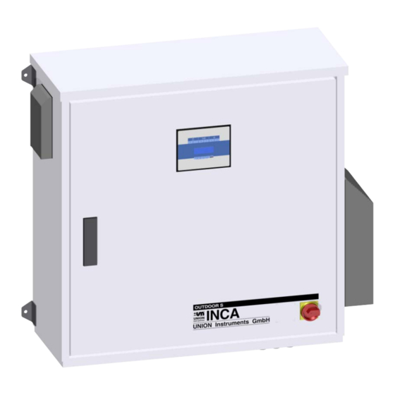
Connections Fig. Product description Connections see Fig. 4.2 Display Door lock, lockable Master switch NOTE Up to 4 process gas lines can be connected. -
Page 18: Fig. 4.2: Connections
Connections Fig. 4.2: Connections Output Process gas Input Process gas 3 Input Calibration gas 1 Input Process gas 4 Input Process gas 1 Input Calibration gas 2 Input Process gas 2 10. Output Condensate Lead-throughs for power supply 11. Output Condensate pressure regulator Input Ambient air 12. -
Page 19: Connection Of Process Gas And Electric Ball Valve
Connections Connection of process gas and electric ball valve Fig. Connection of process gas and electric ball valve Observe the following during installation: • Mount ball valves directly at withdrawal point. • Diameter of outgoing line at ball valve 6 mm. •... -
Page 20: Accessories
Connections 4.1 Accessories WARNING Risk of injury/defective! Use of non-approved accessories can cause defects and be hazardous. This will render the warranty null and void. The operator is then liable for any damage that may occur. Only use original accessories or accessories that have been approved by Union Instruments GmbH. -
Page 21: Transport, Setup And Acceptance
Generally, the process gas analyser is started up by Union Instruments GmbH or service technicians. If it is not transported, set up and started up by Union Instruments GmbH (for example in-house transportation and resale), coordinate the appropriate procedure with Union Instruments GmbH ( Chapter 12 Service). -
Page 22: Ambient Conditions
ATTENTION Ambient conditions during storage and set up. Observe the stipulated ambient conditions. Contact Union Instruments GmbH if the process gas analyser has been stored for more than three months or needs to be operated or stored under ambient conditions other than those specified. -
Page 23: Wall Attachment
Transport, setup and acceptance 5.4.1 Wall attachment The process gas analyser is intended for wall installation. The wall brackets are permanently attached to the housing. The wall on which the process gas analyser is to be installed needs to be sufficiently stable to bear its weight. -
Page 24: Process Gas
Transport, setup and acceptance 5.4.2 Process gas NOTE • The connecting parts need to be clean and free of residue. Impurities can enter the process gas analyser and cause incorrect measurements and/or damage. • The inlet pressure for the gas connections must not exceed the pressure specified on the instruction sticker on the process gas analyser. -
Page 25: Electrical Connection
Transport, setup and acceptance 5.4.3 Electrical connection DANGER Danger from electrical shock! Only a trained electrician may modify the electrical equipment of the process gas analyser in accordance with the relevant guidelines. When the process gas analyser has been opened, the parts identified by the adjacent symbol may still be live even when the master switch has been turned off. -
Page 26: Fig. 5.2: Power Supply X4 Connections
Transport, setup and acceptance Power Supply Connections Fig. 5.2: Power supply X4 connections Relay and analogue outputs Power supply connections X4 Connect the process gas analyser to the power supply in accordance with national regulations via L1, N and PE. -
Page 27: Fig. 5.3: Electrical Connections
Transport, setup and acceptance Electrical connections Fig. 5.3: Electrical connections Relay X10 Profibus Relay for ball valves X13 Depending on the type and equipment used, these are attached to the top hat rail. NOTE Current assignment depends on the configuration, see attached wiring diagram. -
Page 28: Fig. 5.4: Terminal Block X10: Relay Outputs (Number Optional, At Least 3 Contacts)
Transport, setup and acceptance Relay Designation Function Relay K1 INCA operation Relay K2 INCA failure (inverted) Relay K3 Relay Relay output Relay output – assignment of terminal blocks Fig. 5.4: Terminal block X10: Relay outputs (Number optional, at least 3 contacts) -NC –... -
Page 29: Fig. 5.6: Terminal Block X11: Analogue Outputs (Number Optional)
Transport, setup and acceptance Analogue outputs Fig. 5.6: Terminal block X11: Analogue outputs (Number optional) Item Item Function Function Output 1 – signal/signal 4-20 mA Output 5 – signal/signal 4-20 mA 1 GND 5 GND Output 2 – signal/signal 4-20 mA Output 6 –... -
Page 30: Fig. 5.7: Terminal Block X13: Connection Ball Valve
Transport, setup and acceptance Connection ball valve Fig. 5.7: Terminal Block X13: Connection ball valve The electrical connections for the ball valves are established from the left with the first relay - channel 1 – to the right (channel 2 to channel 4). The first two terminals of each relay are assigned in each case. -
Page 31: Fig. 5.8: Remote Control Unit Rcm X15
Transport, setup and acceptance Remote Control Unit RCM Fig. 5.8: Remote Control Unit RCM X15 Pos.- Description bus, connecting internal power supply internal, RS232 connection for PCB-AddOn (Display) via null modem cable connection Fieldbus coupler bus, connecting internal power supply DIP switches Ethernet status LED, LED 1- USB active, LED 2- Fieldbus active, LED 3 - Ethernet active... -
Page 32: Operator Safety Precautions
5.5 Startup after setup WARNING Untrained personnel starting the process gas analyser may endanger people and equipment. Only trained service technicians may start up the analyser. 5.6 Documentation NOTE Union Instruments GmbH recommends keeping a maintenance manual and documenting all jobs and tests. -
Page 33: Startup /Switching On
6 Startup /switching on ATTENTION To establish operational readiness, including of the linked system components, according to the corresponding operating instructions. NOTE The following table contains highly abbreviated steps for starting up after a long downtime. To turn on the process gas analyser after a short downtime, a few steps can be omitted: ... - Page 34 Startup /switching on...
-
Page 35: Description Of The Workplaces/Operating Elements
7 Description of the workplaces/operating elements NOTE This chapter only discusses the elements used by normal operators to operate the process gas analyser. 7.1 Workplaces Fig. 7.1: Workplaces Item Designation Function/Activity Display with status Display status. Main switch Switch on device. -
Page 36: Fig. 7.2: Status Led
Description of the workplaces/operating elements Display status LED The following states are displayed through those LEDs: LED Operation Output state Description flashing Device functionality OK (even Service might be pending) Device functionality is affected by errors, Service flashing message pending flashing Device stopped by fatal error, Error pending Fig. -
Page 37: Operation
8 Operation WARNING Danger of injury! Only use the process gas analyser when all lines have been installed and checked for leaks according to national regulations. -
Page 38: Description Of Display
Operation Description of display 8.1.1 Using the membrane keypad The software controls are operated using a membrane keypad. The displayed buttons can be selected by pressing the key. The menu structures are intentionally flat to enable quick access to functions. ATTENTION Damage to the membrane keypad! The membrane keypad may be damaged if you use other objects to operate it... -
Page 39: Displayarea
Operation 8.1.2 Displayarea Fig. 8.2: Display area Item Designation Function Top display area Display the status and channel information Bottom display area Switch between various measured values with the arrow keys (▼▲►◄). 8.2 Available displays NOTE The available displays and corresponding functions are described below. The navigation path to the displays is indicated by the menu and function keys in the chapter headings. -
Page 40: Menu Structure
Operation 8.2.1 Menu structure NOTE If some of the menu items (framed in red) are changed, this can subsequently influence the measurement results. Main menu Settings Language Password Output data Screen change Parameter ABC built-in EC meas. Cycle Purge time Commands Start measurement Stop measurement... -
Page 41: Navigate With The Arrow Keys Left ◄ And Right
Operation 8.2.2 Navigate with the arrow keys left ◄ and right ► ● The display indicates that the measuring status is active. ● Switch between the measurements by pressing the left ◄ and right ► keys. The asterisk ( ) indicates that a saved value is being displayed. The values are updated in the display depending on the measuring status. -
Page 42: Navigation With Arrow Keys Up ▲ And Down
Operation 8.2.3 Navigation with arrow keys up ▲ and down ▼ NOTE To navigate with the arrow keys up ▲ or down ▼, use the left ◄ and right ► arrow keys to select the display in which the date and time are shown. ●... -
Page 43: Navigation With Esc And Menu
Operation 8.2.4 Navigation with ESC and MENU ● With the MENU key to the main menu. ● Select the submenu with the up ▲ and down ▼ keys. ● Confirm the selection by pressing the MENU key. ● Press the ESC key in the menu to go one level higher. -
Page 44: Measurement Display
Operation 8.2.5 Measurement display ● Select the individual measurements with the plus + or minus - keys. The asterisk ( ) indicates that a saved value is being displayed. The values are updated in the display depending on the measuring status. With continuous measurement, an asterisk is not displayed since the value is measured and updated continuously. -
Page 45: Saved Measured Values
Operation 8.2.7 Saved measured values ● Press the forward or back key to step through the last saved measured values. ● The measured values are identified by the count/date/time. 8.2.8 Display in the warmup phase WARM-UP T(IR) 49.2°C - OK T(POX) 0x0400 - The figure shows the display during the warm-up phase. -
Page 46: Select Language
Operation 8.2.9 Select language ● Select the language with the ▼▲ keys. ● Confirm the selection by pressing the MENU key. Available languages: German, English, Italian and Spanish... -
Page 47: Password
Operation 8.2.10 Password ATTENTION The password has a maximum of four characters. If you forget the password, you cannot change the configuration. ● Enter the password using the▼▲►◄ keys. ● Confirm the entry by pressing the MENU key. - Page 48 Operation...
-
Page 49: Decommissioning/Switching Off
9 Decommissioning/switching off ATTENTION To decommission the process gas analyser and the linked system components according to their operating instructions. NOTE The following table contains the steps for decommissioning the analyser for a long period. If you only wish to switch off the process gas analyser temporarily, a few steps can be omitted: ... - Page 50 Decommissioning/switching off...
-
Page 51: Maintenance
10 Maintenance The measuring quality of the process gas analyser can only be ensured if the service intervals are maintained. 10.1 Preparations The feed lines to linked system components can be closed for servicing purposes. Once operation has been resumed, they need to be reopened. DANGER Serious risk of injury from electricity. -
Page 52: Maintenance Work/Inspection
Maintenance 10.2 Maintenance work/Inspection NOTE The maintenance work must be carried out in accordance with the inspection and maintenance schedule! The type and extent of the wear depends on the individual application and operating conditions. All intervals specified are therefore for guidance only. - Page 53 Maintenance Interval Maintenance/Replacing components (recommended) Half-yearly service and after commissioning Check and, if necessary, update firmware every 6 months version Save the current configuration with INCACtrl every 6 months Annual service Replace integrated filters every 12 months 2-yearly service Replace pump hoses every 24 months Replace flame arrester every 24 months...
- Page 54 Maintenance...
-
Page 55: Troubleshooting
11 Troubleshooting NOTE A distinction is made between the following categories: Possibility of the measured values: Measured values that deviate from the anticipated range last maintenance! maintenance manual! Faults: Faults during operating process To eliminate: Section 11.2, p. 56! 11.1 Preparations The feed lines to linked system components can be closed for servicing purposes. -
Page 56: Changing/Replacing Fuses
Troubleshooting 11.2 Changing/replacing fuses Fuses may only be exchanged by an electrician or service professional. Choose the type approved by Union. 11.3 Messages/malfunctions on the display 11.3.1 Display of messages/malfunctions If errors occur during operation, the control system automatically switches to overview to display priority messages. -
Page 57: Service
12 Service NOTE If you have any questions Union Instruments GmbH will be happy to assist. In case of orders or technical questions, please have the customer number, telephone number for return calls, the type and number of the process gas analyser (see the type plate) and the required spare parts and parts list numbers to hand. - Page 58 Service...
-
Page 59: Associated Documents
13 Associated documents • Declaration of Conformity for flame arrester • Operating and service log • Service documentation, optional • Operating Instructions Ball Valves if installed... - Page 60 Associated documents...
-
Page 61: Disposal
14 Disposal Following decommissioning, the analyser can be returned to Union Instruments GmbH. Suggestion, have Union Instruments GmbH dispose of the process gas analyser. WARNING Serious risk of injury from electricity and exiting gas in the process gas analyser. Before disassembly, disconnect the process gas analyser from the energy supply. - Page 62 Disposal...
-
Page 63: Spare Parts
If components are discontinued or components by different manufacturers are used, request the manufacturer approval by Union Instruments GmbH. Spare parts can be ordered from Union Instruments GmbH: Chapter 12 Service. Note the type and number ( type plate) of the process gas analyser. - Page 64 Spare parts...
-
Page 65: Annex
16 Annex... -
Page 66: Eu Declaration Of Conformity Flame Arrester
Annex EU Declaration of Conformity Flame arrester... - Page 67 Annex...
-
Page 68: Index
Connections .......... 17 with arrow keys ......41, 42 Contact with ESC and MENU ......43 Service ..........57 Union Instruments GmbH ....14 Password ..........47 Personnel and qualifications ....12 Decommissioning ......49, 61 Process gas........... 24 Display ..........39 Proper use .......... -
Page 69: Table Of Figures
Annex Table of figures Fig. 1.1: Type plate (exemplary) ................... 4 Fig. 3.1: Main switch (example) .................. 15 Fig. 3.2: Markings and warnings ................16 Fig. 3.3: Warning note in housing ................16 Fig. 4.1: Product description ..................17 Fig. 4.2: Connections ....................
Need help?
Do you have a question about the INCA6003 and is the answer not in the manual?
Questions and answers