
Subscribe to Our Youtube Channel
Related Manuals for Union Instruments INCA Series


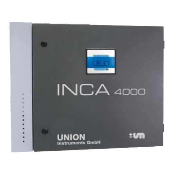
Summary of Contents for Union Instruments INCA Series
- Page 1 INCA Analyzer Series UNION INSTRUCTION MANUAL Instruments GmbH Gas composition measurement of biogas, raw biogas, landfill gas and bio-methane Version: V1.01R06 Stand: 15.03.2010...
-
Page 2: Please Read This Before Proceeding
Read all instructions prior to installing, operating and servicing the instrument. Follow all important notes and cautions marked on and supplied with the instrument. If you do not understand any of the instructions contact your Union Instruments GmbH representative for clarification. -
Page 3: Table Of Contents
UNION Instruments GmbH INCA Analyzer Series – Instruction Manual ABLE OF CONTENTS PLEASE READ THIS BEFORE PROCEEDING! ..............2 Table of contents ........................3 Preface ........................... 7 Purpose ........................7 Technical description ....................7 Remarks ........................7 Safety instructions ......................8 General description .......................10... - Page 4 UNION Instruments GmbH INCA Analyzer Series – Instruction Manual Output option .........................40 Auto-output implementation ..................40 6.1.1 Data structure ....................40 6.1.2 Interface parameter ..................41 6.1.3 Data description ....................41 H-Bus protocol (Master-Slave) ................44 6.2.1 Data structure ....................44 6.2.2 Commands description ..................44 Service and maintenance ....................48 Pumps ........................49...
- Page 5 UNION Instruments GmbH INCA Analyzer Series – Instruction Manual Figures Figure 3-1: Phase transition in standard analyzer ..............11 Figure 3-2: Phase transition in continuously measuring analyzer .........11 Figure 3-3: NDIR module ......................13 Figure 3-4: EC/EC-µPulse module ..................13 Figure 3-5: Parox module .....................14 Figure 3-6: Specific gravity measuring cell, heated and insulated .........14...
- Page 6 UNION Instruments GmbH INCA Analyzer Series – Instruction Manual Tables Table 1: Measurement phases .....................10 Table 2: List of sensor modules ....................12 Table 3: Measurement keys description ................22 Table 4: Example of calibration gases ..................31 Table 5: Calibration points measured by the example of calibration gases ......32 Table 6: Data description ......................43...
-
Page 7: Preface
UNION Instruments GmbH INCA Analyzer Series – Instruction Manual REFACE Purpose The INCA Analyzer Series are a (semi)continuous measuring instruments to analyze gas compositions in biogas, raw biogas, poor gas and bio-methane. With their capability to measure gas components such as CO... -
Page 8: Safety Instructions
UNION Instruments GmbH INCA Analyzer Series – Instruction Manual AFETY INSTRUCTIONS This manual should be reviewed with special attention to all the instructions and cautions before the analyzer is out into operation Power plug and main fuse switch Before opening the analyzer the power plug has to be disconnected from the power supply. - Page 9 UNION Instruments GmbH INCA Analyzer Series – Instruction Manual Application The analyzer has been designed as a process gas analyzer and is not applicable for personnel protection, area monitoring or detection of MAC or UEL limits. All applicable safety regulations must be observed when working with toxic or flammable gases.
-
Page 10: General Description
UNION Instruments GmbH INCA Analyzer Series – Instruction Manual ENERAL DESCRIPTION The INCA Analyzer Series offers a group of gas measurement instruments to analyze gas compositions in different applications such as the production of biogas, raw biogas, poor gas and bio-methane. With their capability to measure gas components such as CO... -
Page 11: Diagrams Of The Phase Transition
UNION Instruments GmbH INCA Analyzer Series – Instruction Manual 3.1.2 Diagrams of the phase transition Measurement Check for Calibration Autocalib. Change channel Purge gas Purge gas calibration Condensate drain Figure 3-1: Phase transition in standard analyzer Measure continuous channels: (e.g. CO... -
Page 12: Sensor Modules
UNION Instruments GmbH INCA Analyzer Series – Instruction Manual Sensor modules The following sensor modules are available in the INCA Analyzer series. Cross Type Variable Principle Accuracy Range Note sensitivity NDIR ±1 % of range 0 – 100 vol.% P ,T compensated (4.26 µm) -
Page 13: Ndir Module
UNION Instruments GmbH INCA Analyzer Series – Instruction Manual 3.2.1 NDIR module The NDIR module is used for measuring CO , CH and other possible hydrocarbon gas. Using non-dispersive infrared (NDIR) technique and dual beam method, the setup of two IR sensors and two IR detectors detects two different wavelengths depending on the type of gas, accuracy and range of the measurement. -
Page 14: Paramagnetic Oxygen Sensor (Parox) Module
UNION Instruments GmbH INCA Analyzer Series – Instruction Manual 3.2.3 Paramagnetic oxygen sensor (Parox) module The Parox sensor measures the oxygen concentration in a gas by using the oxygen paramagnetic properties. The paramagnetic sensor offers better accuracy and is practically insensitive to other gases. -
Page 15: Communication With Pc Using Incactrl
UNION Instruments GmbH INCA Analyzer Series – Instruction Manual Communication with PC using INCACtrl The INCA Analyzer comes with INCACtrl, a software running on MS Windows XP/Vista™ serving as an interface to communicate through a PC with the analyzer. The software serves... -
Page 16: Figure 3-8: Establishing Connection Between Incactrl And Inca Analyzer
UNION Instruments GmbH INCA Analyzer Series – Instruction Manual 4. Click the icon to establish a connection. to establish a connection communication successfully established communication failed Figure 3-8: Establishing connection between INCACtrl and INCA Analyzer If you get an error message, check the modem cable. The COM-port setup should also be checked by deactivating the auto-detect and manually choose the port where the null modem cable is connected. -
Page 17: Saving The Configuration To The Inca Analyzer
UNION Instruments GmbH INCA Analyzer Series – Instruction Manual 3.3.2 Saving the configuration to the INCA Analyzer Note Any change of INCACtrl configuration will only become effective after saving them to the INCA Analyzer. 1. Check the following sign in the INCACtrl. Red cross shows that some changes are... -
Page 18: Figure 3-11: Green Check Mark - Saving Configuration Was Successful
UNION Instruments GmbH INCA Analyzer Series – Instruction Manual 3. The green check mark is shown if the saving was successful. Figure 3-11: Green check mark - saving configuration was successful Page 18 of 59 General description... -
Page 19: System Main Menu
UNION Instruments GmbH INCA Analyzer Series – Instruction Manual YSTEM MAIN MENU Main menu structure of the analyzer can be broke down as: Main menu Settings Language Password Cal. purge gas Output data Communication Parameters Cooler gas temp EC meas. cycle... -
Page 20: Figure 4-2: Display For Continuous Measurement Configuration
UNION Instruments GmbH INCA Analyzer Series – Instruction Manual In the figure above the measuring phase is active and the analyzer will switch to next phase in 4 minutes 57 seconds. Channel 1 of 3 available channels is active and currently measured. -
Page 21: Display Keys
UNION Instruments GmbH INCA Analyzer Series – Instruction Manual Display keys 4.1.1 Menu function keys Six main menu keys are located under the screen: up ▲, down ▼, left ◄, right ► are keys MENU for navigation, for cancel or go back to previous layer and to jump to main menu and also to confirm inputs/commands. -
Page 22: Measurement Data Keys
UNION Instruments GmbH INCA Analyzer Series – Instruction Manual The up ▲ or down ▼ keys are used to show the measured pressures and errors/messages. MEASURING 4:57 Channel : 07/22/2009 14:42:21 Press up ▲ or down ▼ to show the measured... - Page 23 UNION Instruments GmbH INCA Analyzer Series – Instruction Manual MEASURING 4:57 Channel : 07/22/2009 14:42:21 – (Chnl. 1) Pressing of the Gas display key means showing the actual measured concentration of each 10.0 Vol% gas. REMARK: An asterisk mark which is shown in the display S (Chnl.
-
Page 24: Analyzer Display During Warm-Up
UNION Instruments GmbH INCA Analyzer Series – Instruction Manual Analyzer display during warm-up WARMUP T(IR) : 49.2°C - OK T(POX) : 0x0400 - Figure 4-5: Start-up display The analyzer with NDIR (infra red) sensor module or a Parox sensor needs warm-up time (usually 10-20 minutes) to meet their operating temperatures. -
Page 25: Menu Structure
UNION Instruments GmbH INCA Analyzer Series – Instruction Manual Menu structure key takes the display to the main menu system. The menu key up ▲ or down ▼ MENU MENU changes the highlighted menu up or down. Pressing the means execute the highlighted menu. -
Page 26: Settings
UNION Instruments GmbH INCA Analyzer Series – Instruction Manual Settings 4.4.1 Language The language dialog allows the user to select the language of the system. There are three languages available: English, German, and Italian. Settings Language Password ▼ Cal. purge gas Under Settings menu, press ▲... -
Page 27: Calibration Purge Gas (On/Off)
UNION Instruments GmbH INCA Analyzer Series – Instruction Manual 4.4.3 Calibration purge gas (on/off) The „calibration after purge gas‟-option is activated by setting this menu on or off. Settings ▲ Password Cal. purge gas Output option Output data Under Settings menu, press ▲ and ▼ to highlight Cal. -
Page 28: Parameters
UNION Instruments GmbH INCA Analyzer Series – Instruction Manual Parameters 4.5.1 Gas cooler temperature Set the temperature of the gas cooler (only available if gas cooler is installed). Parameters Gas cooler temp EC meas. cycle Under Parameters menu, press ▲ and ▼ to highlight... -
Page 29: Commands
UNION Instruments GmbH INCA Analyzer Series – Instruction Manual Commands 4.6.1 Change channel This command is only active for analyzers with more than one channel (multi-channel analyzer) and allows to request the measurement of a certain channel. Commands Change channel Restart system ▼... -
Page 30: Reset Calibration
UNION Instruments GmbH INCA Analyzer Series – Instruction Manual 4.6.7 Reset calibration Reset to the factory calibration. For each gas measured in the analyzer, the command has to MENU/ . be chosen and the gas must then be selected and confirmed by pressing System info Show the system info. -
Page 31: Calibration
UNION Instruments GmbH INCA Analyzer Series – Instruction Manual ALIBRATION Calibration The analyzer is pre-calibrated by the manufacturer. In the field the analyzer can be re- calibrated using special calibration gases. The calibration gas needs to be connected to the analyzer for manual calibration. -
Page 32: Preparation For Calibration
UNION Instruments GmbH INCA Analyzer Series – Instruction Manual Using those gases, the following calibration points can be measured. Measured variable Calibration point Zero A1,B1,C Span A1,B1 Table 5: Calibration points measured by the example of calibration gases It is not possible to calibrate the CO... -
Page 33: Incactrl Calibration Setting
UNION Instruments GmbH INCA Analyzer Series – Instruction Manual 5.1.3 INCACtrl calibration setting The communication between PC/laptop with the analyzer is performed using a RS-232 connection and INCACtrl software. Connect the RS-232 interfaces of the PC/laptop and the INCA Analyzer using null modem cable. The RS-232 interface of the INCA Analyzer is located on the INCA main board. -
Page 34: Figure 5-4: Incactrl - Calibration Gas Composition
UNION Instruments GmbH INCA Analyzer Series – Instruction Manual 3. Set the composition. The following figures show an example of setting when using calibration gas B1 (100 vol.% CH and 25 ppm H See figure below. Change the “Gas“, “Conc” (concentration) and “Unit” according to the calibration gas you want to use. -
Page 35: Figure 5-6: Incactrl - Setting Of Calibration Points
UNION Instruments GmbH INCA Analyzer Series – Instruction Manual 5. Calibration points. Choose the calibration points according to your calibration gas. In this example, the following points are selected: Zero CO , Span CH , Span H S, Zero O... -
Page 36: Figure 5-8: Saving The Configuration To The Analyzer
UNION Instruments GmbH INCA Analyzer Series – Instruction Manual 7. Save the configuration to the analyzer. Click the following button to save the configuration into the analyzer. Figure 5-8: Saving the configuration to the analyzer Figure 5-9: New configuration is successfully saved to the analyzer 8. -
Page 37: Automatic Calibration
UNION Instruments GmbH INCA Analyzer Series – Instruction Manual 5.1.4 Automatic calibration The analyzer is pre-programmed doing automatic calibration after every purge gas phase. Depending on the setup of the analyzer (continuous or discontinuous measurement), a purge gas phase is run through from every 15 minutes up to 12 hours between the calibration phases. -
Page 38: Manual Calibration
UNION Instruments GmbH INCA Analyzer Series – Instruction Manual 5.1.5 Manual calibration Manual calibration can be performed using the user interface of the display. Under Commands menu, there perform calibration using purge gas. Commands Cal. purge gas Cal. gas I Reset calibration Under the Commands menu, press ▲... - Page 39 UNION Instruments GmbH INCA Analyzer Series – Instruction Manual Note A running calibration can always be interrupted or stopped by choosing Restart system in the display command menu. Note INCACtrl software is always required to set up the calibration gas compositions and the calibration points for the calibration process.
-
Page 40: Output Option
UNION Instruments GmbH INCA Analyzer Series – Instruction Manual UTPUT OPTION The INCA Analyzer can be configured to output the main measurement data through a RS- 232 connection. As an option this data can be distributed to field bus devices such as Profibus-DP, Modbus RTU, etc. -
Page 41: Interface Parameter
UNION Instruments GmbH INCA Analyzer Series – Instruction Manual Using definition: _BYTE represents 1 Byte (8 Bit) _WORD represents 2 Bytes (16 Bit) ST_TIME_INT represents 8 Byte (see below) The structure ST_TIME_INT for the time representation is defined as follows: _BYTE sekunden;... - Page 42 UNION Instruments GmbH INCA Analyzer Series – Instruction Manual 5. Word: n.d. DPI: n.d. Unit: n.d. 6. Word: n.d. DPI: n.d. Unit: n.d. 7. Word: n.d. DPI: n.d. Unit: n.d. 8. Word: n.d. DPI: n.d. Unit: n.d. 9. Word: n.d.
-
Page 43: Table 6: Data Description
UNION Instruments GmbH INCA Analyzer Series – Instruction Manual Change channel / measurement point Calibrate with purge gas Calibrate with calibration gas I Calibrate with calibration gas II Error secondsInState Time in seconds how long analyzer has been in current state (... -
Page 44: H-Bus Protocol (Master-Slave)
UNION Instruments GmbH INCA Analyzer Series – Instruction Manual H-Bus protocol (Master-Slave) 6.2.1 Data structure Communication with analyzer with a protocol with the following data structure: Block length N DATA CRC16 WORD N*WORD WORD Not included in the data structure of... - Page 45 UNION Instruments GmbH INCA Analyzer Series – Instruction Manual Command Bytes Description 0x0000 Anybus Flush (4)* Format : 0x0001 0x0000 (CRC16)* Response : 0x0001 0x0000 (CRC16)* As dummy instruction during connection of Anybus. It is necessary since it is not allowed to have two identical commands in a row using Profibus-DP.
- Page 46 UNION Instruments GmbH INCA Analyzer Series – Instruction Manual 3.Word: Channel 1-H DPI: no Unit: ppm 4.Word Channel 1-H DPI: no Unit: ppm 5.Word Channel 1-O -Parox DPI: yes(2) Unit: vol.% 6.Word: Channel 2-CH DPI: yes(2) Unit: vol.% 7.Word: Channel 2-CO DPI: yes(2) Unit: vol.%...
-
Page 47: Table 7: Commands Description
UNION Instruments GmbH INCA Analyzer Series – Instruction Manual Channel = 0…9 0x0032 --not defined -- 0x0033 --not defined -- 0x0040 Read firmware version (6)* Format : 0x0032 0x0040 (CRC16)* Response : 0x0002 0x0040 SWVERSION (CRC16)* (U_WORD) Exponent -2 i.e. 100 == Version 1.00 (V1.00) -
Page 48: Service And Maintenance
UNION Instruments GmbH INCA Analyzer Series – Instruction Manual ERVICE AND MAINTENANCE Warning The power plug and gas flow must be disconnected during maintenance and service. Warning Gas leak may possibly occur in case of installation or service failure with both health hazards and corrosion damage possibilities. -
Page 49: Pumps
UNION Instruments GmbH INCA Analyzer Series – Instruction Manual Interval Maintenance work/replacement Every 6 months All gas connections in the analyzer should be leak tested Every 1 year Air filter Water trap Sensor replacement: sensor (for continuous measurement) S sensor... -
Page 50: Sensor Modules
UNION Instruments GmbH INCA Analyzer Series – Instruction Manual Sensor modules 7.2.1 Electrochemical sensor The lifetime of the electrochemical sensors (H S, H and O ) depends on the gas concentrations in the process gas. S and H The average lifetime of the H... -
Page 51: Spare Parts List
UNION Instruments GmbH INCA Analyzer Series – Instruction Manual PARE PARTS LIST Assembly group diaphragm gas pump MVG accessories hoses Weight: 675 grams Description : Assembly group diaphragm gas pump Item number Assembly group diaphragm air pump Accessories hoses Weight: 550 grams... - Page 52 UNION Instruments GmbH INCA Analyzer Series – Instruction Manual Flame arrestor - maximum pressure: 1.1 bar absolute - maximum temperature 60 °C - explosion group IIC Weight: 200 grams Description : Flame arrestor SS Item number Specific Gravity Sensor - heated - +/-15V / 7VA - Range 0,2 –...
-
Page 53: Appendix
UNION Instruments GmbH INCA Analyzer Series – Instruction Manual PPENDIX Abbreviations Electrochemical Infrared Maximum acceptable concentration NDIR Non-dispersive infrared PTFE Polytetrafluoroethylene Specific gravity Upper explosion limit Errors and events list 9.2.1 State machine errors Error code Display description Full description... -
Page 54: Errors Reading From Or Writing To Eeprom
UNION Instruments GmbH INCA Analyzer Series – Instruction Manual 0x0210 COMM CMD NOT FOUND Bus protocol configuration error A command was requested which is not supported/defined by bus protocol 0x0211 COMM CMD TIMEOUT Bus protocol communication error REC. HEADER Receiving header of protocol failed due to a timeout... -
Page 55: Sensor Errors
UNION Instruments GmbH INCA Analyzer Series – Instruction Manual 0x0223 COMM SAVE DATA Reading saved EEPROM (sensor/slave) data error READ NOT AVLB. Function not supported by slave 0x0224 COMM SAVE DATA Reading saved EEPROM (sensor/slave) data error READ RANGE Too much data was requested from EEPROM... - Page 56 UNION Instruments GmbH INCA Analyzer Series – Instruction Manual 0x030A SENS CAL STATUS SPAN EC1 Span calibration could not be performed on EC channel 1 --- currently not used --- 0x030B SENS CAL STATUS ZERO EC2 Zero calibration could not be performed on EC channel 2...
-
Page 57: Command List And Task Request List Errors
UNION Instruments GmbH INCA Analyzer Series – Instruction Manual 0x038D SENS EC CALIB Span calibration for EC sensor aborted ABORT SPAN 0x038E SENS EC CALIB Mixer calibration for EC sensor aborted ABORT MIXER 0x038F SENS EC CALIB Calibration for EC sensor aborted ABORT NO DEF. -
Page 58: Menu Errors
UNION Instruments GmbH INCA Analyzer Series – Instruction Manual calibration 0x0483 DYN STR. Firmware development error LIST OVERFLOW Overflow when creating dynamic signal list 9.2.6 Menu errors Error code Display description Full description 0x0500 MENU OBJECT OVERFLOW Firmware development error... -
Page 59: Table Of Contents
UNION Instruments GmbH INCA Analyzer Series – Instruction Manual 9.2.8 SD card errors Error code Display description Full description 0x0700 SDCARD POWER ON CMD0 Power on command failed 0x0701 SDCARD INITIALIZE CMD1 Initialize command failed 0x0702 SDCARD READ SECT. Read section from card failed...
Need help?
Do you have a question about the INCA Series and is the answer not in the manual?
Questions and answers