
Subscribe to Our Youtube Channel
Related Manuals for Union Instruments CWD3000 EXP


Summary of Contents for Union Instruments CWD3000 EXP
- Page 1 Translation of operating instructions Explosion-Protected Combustion Calorimeter CWD3000 EXP Mrz-2019 V1.02...
- Page 2 UNION Instruments GmbH Zeppelinstraße 42 76185 Karlsruhe Germany +49 (0)721-680381-0 +49 (0)721-680381-33 support@union-instruments.com http://www.union-instruments.com 02608199964 © 2019 Mrz-2019 V1.02 This documentation is protected by copyright. All rights, in particular the rights of translation, reprint, extraction of figures, radio transmission, and duplication by photomechanical or other means and of storage in data processing systems, in whole or in part, are reserved.
-
Page 3: Table Of Contents
Table of contents Technical data ....................... 5 Name plate ........................5 Dimensions ........................6 Device overview ......................7 Explosion marking as per EC type examination ............7 Marking as per the IECEx scheme ................7 Voltage supply ......................7 Interfaces ........................8 Heating value measurement display times .............. - Page 4 Technical data 6.3.5 Electrical connection ....................43 6.3.6 Electrical interfaces ....................46 6.3.7 Connector assignment for input/output signals ............47 6.3.8 Removing/attaching transport securing devices............50 Owner safety precautions ................... 52 Documentation ......................52 Commissioning/Switching on ..................53 Description of the work stations/operator control elements ........55 Operation ........................
-
Page 5: Technical Data
1 Technical data 1.1 Name plate Fig. 1.1: Name plate (example) Device description and product code Technical information Approval information (example) -
Page 6: Dimensions
Technical data 1.2 Dimensions Fig. 1.2: Housing dimensions Weight: approx. 140 kg... -
Page 7: Device Overview
Technical data 1.3 Device overview Fig. 1 Markings and warning information 1. Explosion-protection warning information 2. Warning information for electricity 3. Name plate 1.4 Explosion marking as per EC type examination Explosion marking: II 2G Ex pxb IIC T4 Gb EC type examination: BVS 19 ATEX 012 X Ambient temperature:... -
Page 8: Interfaces
Technical data 1.7 Interfaces Interfaces: RS232, Profibus, Fieldbus, Industr. Ethernet Analog outputs: 3, 4 – 20 mA for heating value, Wobbe index and density Digital outputs: 3 relays 1.8 Heating value measurement display times 90% time: CWD3000: ≤ 15 seconds 1.9 Gas inputs Process gas: Calibration inputs:... - Page 9 Technical data NOTE Provide sufficient buffer volume for ignition protection gas; volume is dependent upon the switching frequency of the compressor and the possible operating time without the compressor. UNION recommends compressed air of class 533 as per ISO 8573-1 corresponding to solids of 40 μm (class 5)/dew point of –20°C (class 3)/oil quality of 1 mg/m³...
-
Page 10: Combustion Gas
Technical data 1.12 Combustion gas NOTE The combustion gas must be free of condensate, dust and other contaminants, such as naphthalene. Gas connection inlet Max. 500 bar, min. 20 mbar pressure: Combustion gas 30 – 40 l/h (min. rel. density 0.50 with 0.55 mm consumption: nozzle) Calibration gas... -
Page 11: Fig. 1.4: Measuring Ranges And Accuracy
Technical data Application Measuring accuracy Application (process gas type) [Wobbe index] Applic. No. Measuring range Series Series (Wobbe index) CWD2500 CWD3000 Mixed gas (BFG + COG) 5.2 – 10.5 MJ/m3/1.4 – 2.9 kWh/1,250 – 2,500 ±2% FS Not used kcal/130 – 260 BTU/ft Mixed gas (BOFG + NG) 4.2 –... -
Page 12: Ambient Conditions Of Installation Location
Technical data 1.14 Ambient conditions of installation location NOTICE Use of the combustion calorimeter outside the approved range of ambient conditions results in voiding of the approval! Risk of serious accidents. Installation location: Protect against direct sunlight and ensure sufficient shade. -
Page 13: Eu Declaration Of Conformity
Produkte/hereby declares, that the following named products: Produktbezeichnung: Verbrennungskalorimeter Gerätegruppe: CWD3000 EXP Product name: Calorimeter device group: CWD3000 EXP Explosionsgruppe: II 2G Ex pxb IIC T4 Gb EG-Baumusterprüfung: BVS 19 ATEX 012 X Explosion group:... - Page 14 EU Declaration of Conformity...
-
Page 15: Safety Instructions
3 Safety instructions 3.1 Warning information and symbols These operating instructions use the following nomenclature and symbols for especially important information: DANGER The combustion calorimeter is approved for use in hazardous areas as per the EC type examination/IECEx certification. In these operating instructions, information on possible dangerous situations which could arise in hazardous areas is marked with the symbol shown here. -
Page 16: Principle, Intended Use
The device is based on ignition type “p” – pressurized enclosure. Compressed air is used as the ignition protection gas. The calorimeter CWD3000 EXP is intended for use in weather-proof areas and for fixed mounting to a wall and fixed installation (temperature range: 10°C – 50°C). -
Page 17: Personnel And Qualification
Safety instructions 3.5 Personnel and qualification Gas connections and work on the electrical equipment of the combustion calorimeter may only be carried out by a professional in compliance with safety provisions, especially for hazardous areas. -
Page 18: Safety Instructions
Safety instructions 3.6 Safety instructions 3.6.1 General safety instructions WARNING Only operate the combustion calorimeter when all protective equipment is present and operational! Further safety information: Preceding the corresponding sections! 3.6.2 Information on specific hazards DANGER • After installation, all gas-conveying parts must be checked for proper seal according to national regulations! •... -
Page 19: Information On Explosion Protection
Safety instructions 3.7.1 Information on explosion protection WARNING When opening, observe the instructions on explosion protection in hazardous areas! May be opened by specialists only! The device must first be flushed after opening the housing and switching on again! Minimum flow volume is 16,000 l/h of compressed air at 4.5 – 5 bar! You must wait for at least 5 minutes after separation of the power supply before any doors of the housing may be opened. -
Page 20: Performing A Workplace Risk Assessment
Further technical developments may result in deviations from these operating instructions. If you would like more information or if you encounter problems that are not covered in detail in this manual, contact us at the following address: UNION Instruments GmbH Zeppelinstraße 42 76185 Karlsruhe... -
Page 21: Protective Equipment
4 Protective equipment The CWD3000 EXP is supplied without a main switch, as the owner must provide suitable equipment for separating the supply voltage as part of the voltage supply equipment. 4.1 Pressurized enclosure ignition protection type Pressurized enclosure ignition protection type “p” as per IEC EN 60079-2 enables the operation of electrical devices in explosive atmospheres in which the creation of a hazardous gas atmosphere in the device is prevented. -
Page 22: Protective Housing With Doors
Protective equipment 4.2 Protective housing with doors Pressure-tight housing which prevents the penetration of ambient atmosphere when closed and ready for operation. Fig. 4.1: Housing, rooms with lockable doors Protective covers (doors) of the housing separate electrical, ignitable modules and hot surfaces from the environment. -
Page 23: Thermal Cutoff
Protective equipment 4.5 Thermal cutoff NOTE The tripping temperature of the thermal cutoff is 72°C. When tripped, the thermal cutoff separates the 24 V voltage supply from the solenoid valves. The device is separated from the combustion gas. Solenoid valves are closed in the current-free state. -
Page 24: Pressure Switches
Protective equipment 4.7 Pressure switches Monitor differential pressures of the media in the housing, deenergize the device if limits are violated and solenoid valves at the combustion gas inlet close. Fig. 4.4: Depiction of pressure switches (example) -
Page 25: Markings And Warning Information
Protective equipment 4.8 Markings and warning information Fig. 4 Markings and warning information (example) Designation Warning information: hot surface (internal) Warning information: electricity (external) Warning information: risk of explosion When opening, observe the instructions on explosion protection in hazardous areas! May be opened by specialists only! The device must first be flushed after opening the housing and switching on again! Minimum flow volume of 16,000 l/h of compressed air at 4.5 –... -
Page 26: Fig. 4.6: Warning Information On Electrical Connection Plate (Example) Interior, Cell
Protective equipment Fig. 4 Warning information on electrical connection plate (example) Interior, cell 3 – voltage supply Name plate with explosion marking Fig. 4 Name plate with ATEX/IECEX marking (example) NOTE Malfunction in case of interruption of ignition protection gas supply/compressed air! When a valve for shutting off the ignition protection gas supply is installed by the owner, a sign is to be posted at that location. -
Page 27: Description And Connections
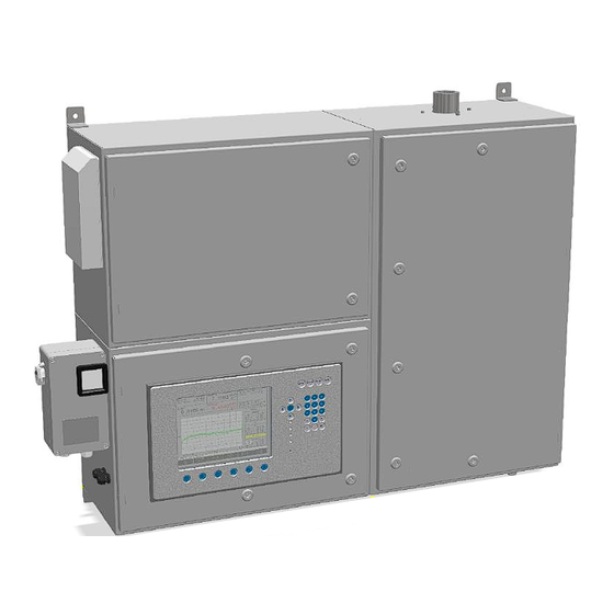
5 Description and connections 5.1 External overview and housing connections Fig. 5 Device overview Item Designation Flue gas and cooling air outlet Wall mounting eyelet, 4x Door of cell 2 with 7 hasps Ignition protection gas/compressed air inlet Signal line cable glands of cell 2 Display and operating unit, door of cell 3 with 4 hasps Control unit with electrical voltage supply connection Gas inlets (max. -
Page 28: Interior Connections And Components
Description and connections 5.2 Interior connections and components Fig. 5.2: Housing with no doors (example showing carrier gas option) Item Designation Gas inlet block with solenoid valves Carrier gas processing (optional) Combustion gas/exhaust air outlet Pressure switches, 3x Thermal element with combustion chamber Ignition transformer Precision pressure controller with mixer block Digital valve, compressed air infeed with silencer... -
Page 29: Accessories
Using non-approved accessories may cause damage and put persons at risk. Such use will void the warranty! The owner is then liable for any resulting damage! Pay attention to the ATEX type examination/IECEx certificate! Only use genuine accessories or accessories approved by UNION Instruments GmbH! - Page 30 Description and connections...
-
Page 31: Transport, Installation And Acceptance
The combustion calorimeter is generally commissioned by UNION Instruments GmbH or correspondingly qualified service technicians. If it is not commissioned by UNION Instruments GmbH (e.g. internal transport/resale), a suitable procedure must be agreed upon with UNION Instruments GmbH ( Chapter 13 Service). - Page 32 Transport, installation and acceptance WARNING Risk of injury/damage! The protective function of the housing can be adversely affected by transport damage. In case of damage to the transport packaging or signs of improper transport, closely inspect the housing!
-
Page 33: Environmental Conditions
6.2 Environmental conditions NOTICE Comply with environmental conditions for storage and installation! Contact UNION Instruments GmbH if the combustion calorimeter is stored for longer than 3 months or must be operated or stored outside the prescribed ambient conditions! 6.2.1 Storage conditions NOTE Ensure that the combustion calorimeter is free of gas/moisture residue. -
Page 34: Installing And Connecting
Transport, installation and acceptance 6.3 Installing and connecting NOTICE If there is an “X” after the certificate number, pay attention to the conditions on installation and operation in the type examination. The local installation provisions, especially the requirements of IEC/EN 60079- 14, are to be observed. -
Page 35: Installation Location
Transport, installation and acceptance 6.3.1 Installation location The installation location of the combustion calorimeter must meet the following conditions: Carry out installation in accordance with the conditions of the explosion marking. Clean environment suitable for gas-analysis/measurement purposes. Mounting to a solid wall – ensure sufficient load-bearing capacity of the wall. Working space on the left-hand side of at least 60 cm, and on the right side at least 50 cm. -
Page 36: Wall Mounting
Transport, installation and acceptance 6.3.2 Wall mounting WARNING Risk of injury due to the weight of the device! For weight, see technical data! Specify measures to prevent the device from falling down and use suitable hoisting devices! The combustion calorimeter is intended for mounting to a solid wall. There are four 11 mm fastening eyelets on the housing ∅. -
Page 37: Gas Connections
Transport, installation and acceptance 6.3.3 Gas connections DANGER Risk of explosion! Non-approved lines and insufficient connections pose a hazard! Gas connections may only be installed by qualified personnel! Check for proper sealing of connections and ensure this during operation! NOTE •... -
Page 38: Fig. 6.2: Ignition Protection Gas Connection, Compressed Air, 6 Mm Screw Fitting
Transport, installation and acceptance Fig. 6.2: Ignition protection gas connection, compressed air, 6 mm screw fitting 1 Compressed air/ignition gas connection, 6 mm pipe fitting, pressure: 4.5 – 5 bar, use preinstalled pressure controller. Two compressed air pressure controllers (external and in device). Set external controller to no higher than 5 bar. - Page 39 Transport, installation and acceptance 6.3.3.3 Carrier gas supply NOTE • For combustion gases that do not have stable combustion, a carrier gas can be added. • Carrier gases maintain combustion and make no increased contribution to the combustion value of the combustion gas. •...
-
Page 40: Fig. 6.3: Connections For Process, Calibration, Carrier And Test Gases, 6 Mm Screw Fitting
Transport, installation and acceptance Fig. 6.3: Connections for process, calibration, carrier and test gases, 6 mm screw fitting Number of connections optional, 1 shows input of gas from the top down Carrier gas I5.2 Input support gas Test gas I5.1 Input test gas Calibration gas 2 I2.3... -
Page 41: Fig. 6.4: Flue Gas/Exhaust Air Connection
Transport, installation and acceptance 6.3.3.5 Flue gas/Exhaust air WARNING Risk of serious injury from escaping flue gases! Flue gases must be discharged safely! • For flue gases containing CO, H and H S, a safe environment must be • ensured! NOTE Flue gases/residual heat must be discharged protected from air draft and without interruption through a vent. -
Page 42: Opening And Closing Of The Housing Doors
Transport, installation and acceptance 6.3.4 Opening and closing of the housing doors DANGER Risk of explosion! Damaged seal/improper closing pose a hazard! Explosion protection is no longer guaranteed if seals are damaged or doors are closed improperly! WARNING Risk of severe injury – Housing is overpressurized! Switch the device off first, then shut off the ignition gas supply and finally •... -
Page 43: Electrical Connection
Transport, installation and acceptance 6.3.5 Electrical connection DANGER Risk of electric shock! Changes to the electrical equipment of the combustion calorimeter may be carried out only by skilled electricians in accordance with the electrotechnical rules. Parts of the open combustion calorimeter marked with the adjacent symbol may still carry voltage even when the main switch is switched off! If required, separate the combustion calorimeter from the supply network! DANGER... -
Page 44: Voltage Supply
Transport, installation and acceptance 6.3.5.1 Voltage supply Fig. 6.5: Electrical connection, control unit (example) Connect the combustion calorimeter to the voltage supply using connections 19, 20 – 21, 22 and PE (23, 24, 25 and 26) of the control unit in accordance with national requirements. - Page 45 Transport, installation and acceptance WARNING After the line voltage is switched off, the device capacitors still carry voltage for up to 5 minutes! This time must be allowed to elapse before starting work on the high-voltage electrical system. The specifications of the VDE, the local and regional safety regulations, and the factory-internal safety rules must be complied with at all times during work on the combustion calorimeter! NOTE...
-
Page 46: Electrical Interfaces
Transport, installation and acceptance 6.3.6 Electrical interfaces WARNING Endangerment of people and equipment when the combustion calorimeter is commissioned by non-instructed personnel! Allow only instructed/trained service technicians to carry out commissioning! DANGER Risk of explosion! Electrical interfaces - only connect analog signals and relays using the disconnector unit supplied! Fig. -
Page 47: Connector Assignment For Input/Output Signals
Transport, installation and acceptance 6.3.7 Connector assignment for input/output signals Fig. 6.7: Connector assignment of input/output IO external type 06 WARNING Do not connect to line voltage! Only operate outputs (relay, analog and digital) and inputs with safety extra-low voltage! - Page 48 Transport, installation and acceptance Connector X14 relay outputs Digital output Pin/Connector X14 Function Status display Common Process Normally open Normally closed Common Maintenance Normally open Normally closed Common Filter change Normally open Normally closed 10 Common Fault 11 Normally open 12 Normally closed 13 Common Function, optionally...
- Page 49 Transport, installation and acceptance Connector X3 digital control inputs Control Pin/Connector X3 Function Status inputs display diode Start measurement D 25 Start measurement Start calibration D 24 Start calibration Function, optionally D 23 assigned if applicable Function, optionally D 22 assigned if applicable Function, optionally D 21...
-
Page 50: Removing/Attaching Transport Securing Devices
Transport, installation and acceptance 6.3.8 Removing/attaching transport securing devices NOTE Before commissioning/transport of the combustion calorimeter, it must be ensured that all transport securing devices are removed/attached. The following transport securing devices must be removed/attached within the combustion calorimeter: Fig. 6.8: Transport securing devices (example shown) Item Component... -
Page 51: Fig. 6.9: Transport Securing Devices Of Pressure Controller
Transport, installation and acceptance Transport securing device in the pressure controller Fig. 6.9: Transport securing devices of pressure controller Order of removal/attachment of Transport securing device transport securing device Remove the retaining belts. • Open the protective flap (screw • Transport securing device of pressure closure). -
Page 52: Owner Safety Precautions
In case of toxic gases, mark outlet location of discharged flue gas/off-gas with a warning! • Tripping hazard from improperly routed supply lines! 6.5 Documentation NOTE UNION Instruments GmbH recommends keeping a maintenance log and documenting all work and tests. -
Page 53: Commissioning/Switching On
7 Commissioning/Switching on NOTICE In order to establish start readiness, also establish the start readiness of linked system components according to their operating instructions! NOTE For initial commissioning or before an extended operating shutdown, back up the device configuration. Have the backup made by service technicians or in response to a special service instruction. - Page 54 When the combustion calorimeter has been switched off only temporarily, production can be resumed! During startup, the device is first flushed with compressed air. Following this rinsing and once overpressure is reached, the control unit activates voltage to the combustion calorimeter. The CWD3000 EXP starts up.
-
Page 55: Description Of The Work Stations/Operator Control Elements
8 Description of the work stations/operator control elements NOTE This chapter contains only elements for operation of the combustion calorimeter by the normal operator. Fig. 8.1: Work stations (example) Item Designation Function/Activity Display Status display and calorimeter operation Control unit Status display and operate control unit... - Page 56 Description of the work stations/operator control elements...
-
Page 57: Operation
9 Operation WARNING Risk of injury! Only operate the combustion calorimeter when all lines are installed and checked for proper seal in accordance with the country-specific regulations! 9.1 Operation of membrane keyboard/Description of display The software controller is operated using a membrane keyboard. The buttons shown can be selected by a key press. - Page 58 Operation Item Designation Function Numeric display Output of current measured values Display field Information field Arrows/Enter Arrow keys enable movement to an input field. The Enter key confirms the entered value. Menu Menu key returns you to the main menu from any other menu level.
-
Page 59: Basic Operation
Operation 9.2 Basic operation The keys described in the following are used for operation of the combustion calorimeter on the part of the software. Symbol Function Back: Causes the menu to jump to the next higher menu level all the way •... -
Page 60: General Information
Operation 9.4 General information Fig. 9.2: General information Display Information (example values) V 4.44R16 Version number of the software Process Current status of the device (e.g. START, STOP, Process, Cal.) 26.02.2019 09:24:46 Current date/time Temperature of cooling air at thermoelectric battery input Temperature of cooling air at thermoelectric battery output... -
Page 61: Fig. 9.3: Information On Overpressure Differential Pressure
Operation Fig. 9.3: Information on overpressure differential pressure Display Information (example values) dp air Pressure at thermal pipe aperture – housing overpressure to combustion air pressure differential dp wobbe Pressure at density cell – housing overpressure to combustion gas pressure differential... - Page 62 Operation...
-
Page 63: Menu Structure
Operation 9.5 Menu structure Main Menu ......................... 64 9.6.1 Main Menu - Options ....................65 Main Menu - Options - I/O ..................66 Main Menu - Options - I/O - Analog Outputs ............. 67 Main Menu - Options - I/O - Digital Outputs ............68 Main Menu - Options - I/O - mA display ............ -
Page 64: Main Menu
Operation 9.6 Main Menu The main menu is the standard display during active operation. The following submenus are accessed from the main menu: Options • Trend • • Eventlist • Device Info... -
Page 65: Main Menu - Options
Operation 9.6.1 Main Menu - Options Configuration option for the following parameters: • Analog outputs • Digital (relay) outputs • mA display • Digital inputs • Display Calibration Configuration option for the following parameters: • Configuration of calibration gas • Automatic calibration Automatic calibration 2 •... -
Page 66: Main Menu - Options - I/O
Operation Main Menu - Options - I/O Options for configuration for the following parameters: Analog outputs • • Digital outputs • mA display Digital inputs • Display •... -
Page 67: Main Menu - Options - I/O - Analog Outputs
Operation Main Menu - Options - I/O - Analog Outputs The mA signals are configured in this menu. The following must be observed for this: Units: xxx/m ³ correspond to a gas temperature of 0°C and a barometric pressure of 1,013 mbar. xxx/Sm ³... -
Page 68: Main Menu - Options - I/O - Digital Outputs
Operation Main Menu - Options - I/O - Digital Outputs Digital signals (relay outputs and floating change-over contacts) are configured in this menu. The following must be observed for this: Zero position: The zero position of the digital outputs can be freely selected: low/high. Process: The combustion gas solenoid valve is open, and the flame is burning. - Page 69 Operation Fault: Device is no longer usable because Air differential pressure is too low (< 3.5 mbar) Sensor break (PT100, thermoelectric battery or temperature at burner is too high) Gas pressure is too low Operation: The flame is burning. Thermoelectric voltage of process or calibration gas is greater than the ignition threshold.
-
Page 70: Main Menu - Options - I/O - Ma Display
Operation Main Menu - Options - I/O - mA display The mA values for the currently active outputs are displayed in this menu. With the mA display key, all channels can be displayed one after the other. The value can be obtained from the “General information”... -
Page 71: Main Menu - Options - I/O - Digital Inputs
Operation Main Menu - Options - I/O - Digital Inputs Various digital signals are configured in this menu. The following must be observed here: The pin assignment is preassigned. Section 6.3.7 ! Signals Zero position Contact CWD3000 open Calibration starts high closed No calibration... -
Page 72: Main Menu - Options - I/O - Display
Operation Main Menu - Options - I/O - Display The display of measured values is configured in this menu. A signal and a unit are assigned to each of the four display windows. -
Page 73: Main Menu - Options - Calibration
Operation Main Menu - Options - Calibration In this menu, the calibration values are configured and calibration can be started manually (Calibrate). -
Page 74: Main Menu - Options - Calibration - Configuration Of Calibration Gas
Operation Main Menu - Options - Calibration - Configuration of calibration gas The calibration gas is configured in this menu. The following must be observed here: The calibration gas is input as a Wobbe index (Wobbe i and Wobbe s) and as a relative density. -
Page 75: Main Menu - Options - Calibration - Automatic Calibration
Operation Main menu - Options - Calibration - Automatic calibration The automatic calibration is configured in this menu. The following must be observed here: Input: Day is a list field (Su, Mo, Tu, We etc.). Time and Cycle are value fields. Duration of calibration: Depending on the device type, the calibration duration is 10 –... -
Page 76: Main Menu - Options - Calibration - Automatic Calibration 2
Operation Main menu - Options - Calibration - Automatic calibration 2 The automatic calibration that is defined by a situation is configured in this menu. Criterion 1: Automatic calibration after restart. Criterion 2: Automatic calibration at a defined change in ambient temperature compared to the last calibration. -
Page 77: Main Menu - Options - Calibration - Calibration Limits
Operation Main menu - Options - Calibration - Calibration limits The calibration tolerances are set and the deviations from the base calibration are displayed in this menu. If the calibration values exceed the defined tolerances, this is indicated as a calibration deviation for digital outputs. -
Page 78: Main Menu - Options - System
Operation Main menu - Options - System The basic configurations of the device, such as ignition, time of day, language and code key, are specified in this menu. -
Page 79: Main Menu - Options - System - General
Operation Main menu - Options - System - General The “Change signals after holding” command causes a smooth transition after calibration or removal of the signal holding state. A sudden rise or fall of the measured value in the analog output signal is avoided. The continuous transition is specified in seconds. - Page 80 Operation Operation delay: The “Operation” relay output is activated only after the delay time elapses. Minimum internal pressure: When the minimum internal pressure is undershot, the device goes to STOP state; default value is 8 mbar. Internal pressure warning threshold: Below the warning threshold, insufficient gas is signaled for internal pressure and service.
-
Page 81: Main Menu - Options - System - Ignition
Operation Main menu - Options - System - Ignition NOTE The combustion calorimeter can only be ignited when the door is closed. The ignition monitoring is configured in this menu. The following must be observed here: Single ignition or interval ignition must be chosen. Single ignition: After device start and the flushing time period (10 s), the ignition starts for the maximum set ignition duration. -
Page 82: Main Menu - Options - System - Load Factory Settings
Operation Main menu - Options - System - Load factory settings The factory settings are loaded with this key. Main menu - Options - System - CSV Export Three files are exported as an ASCI file with this key: 30 min at 1-second intervals, 3 hours at 10-second intervals and 5 days at 1-minute intervals. -
Page 83: Main Menu - Options - System - Settings
Operation Main menu - Options - System - Settings Main menu - Options - System - Settings – Date/Time The date and time are set in this menu. Increments selected numbers Decrements selected numbers Moves one field left Moves one field right... -
Page 84: Main Menu - Options - System - Settings - Language
Operation Main menu - Options - System - Settings - Language The Language menu item contains 10 submenus for inserting, copying and correcting various languages, even those that have to be represented by bitmaps (e.g. Chinese). Languages can be downloaded onto a memory stick, corrected and then re-imported to the combustion calorimeter. -
Page 85: Main Menu - Options - System - Settings - Password
Operation Main menu - Options - System - Settings - Password The password is changed in this menu. The following must be observed here: Factory password: The combustion calorimeter is delivered with factory password of 0. This can be changed, if necessary. Unlock time: This time specifies when the system will be locked and the password must be re- entered. -
Page 86: Main Menu - Options - System - Settings - Change Color
Operation Main menu - Options - System - Settings - Change color The display colors can be changed here. -
Page 87: Main Menu - Options - System - Settings - Hardware 1
Operation Main menu - Options - System - Settings - Hardware 1 NOTE Only change this menu in consultation with the manufacturer. The parameters for a multi-range measuring device are configured in this menu. -
Page 88: Main Menu - Options - Service
Operation Main menu - Options - Service NOTE Only change this menu in consultation with the manufacturer. The device is provided with a default password at the factory for service mode, with which the owner must specify handling! The menu is password-protected. Setting for service only. The device is provided with a default password, 0721, with which the owner must specify handling! The serial interface can be activated with OK and Enter using the menu sequence... -
Page 89: Main Menu - Trend
Operation 9.6.2 Main menu - Trend The graphics are configured in this menu. The following must be observed here: Up to three different curves in various colors can be displayed. Selection: A selection can be made from the following parameters: •... -
Page 90: Main Menu - Graphic - Select Time
Operation Main menu - Graphic - Select time The diagram can be optimally designed. The increments for increasing and reducing are programmed to obtain a resolution for this purpose. The diagram is subdivided into 10 segments on the x-axis. The segment time and the total displayed time can be set as follows: Increase segment time Reduce segment time... -
Page 91: Main Menu - Graphic - Select Value
Operation Main menu - Graphic - Select value Values for the curves can be set in this menu. The curves can be viewed as follows: Ref y-value linearly to y-axis Ref y-value linearly from y-axis dy-value compressed y-axis dy-value stretched y-axis... -
Page 92: Main Menu - Graphic - Select Signal
Operation Main menu - Graphic - Select signal Signals for the curves can be selected in this menu. Example signals: Wobbe i Heating value mVSA Frequency T amb Wobbe s Combustion p Wobbe T in value Main menu - Graphic - Select unit •... -
Page 93: Main Menu - Graphic - Select Curve
Operation Main menu - Graphic - Select curve Individual curves can be selected in this menu in order to change parameters. -
Page 94: Main Menu - Event List
Operation 9.6.3 Main menu - Event list NOTE The event list stores all events that are of interest for operation and service of the device. A total of 1,000 events can be stored. Show all: All events... - Page 95 Operation Show startup: Selection of the start events Show calibration: Selection of the calibration events...
-
Page 96: Main Menu - Device Information
Operation 9.6.4 Main menu - Device information NOTE The values shown are very important for remote diagnostics when errors occur and can be loaded onto the USB memory stick and sent to the manufacturer by email (e.g. using a screenshot; see CSV keyword index). Device data: Type •... -
Page 97: Decommissioning/Switching Off
10 Decommissioning/Switching off WARNING Endangerment of people when the combustion calorimeter is decommissioned by non-instructed personnel! NOTICE Endangerment of equipment when the combustion calorimeter is decommissioned by non-instructed personnel! To decommission the combustion calorimeter, you must decommission the linked system components according to their operating instructions as well! NOTE The following table contains steps for decommissioning for extended periods. - Page 98 Decommissioning/Switching off...
-
Page 99: Maintenance
11 Maintenance When carrying out work in hazardous areas, take the relevant safety precautions. The quality of measurements and availability of the combustion calorimeter can only be guaranteed when the maintenance intervals are adhered to. 11.1 Preparations Supply lines of linked system components can be closed for maintenance purposes. -
Page 100: Maintenance/Inspection
Maintenance 11.2 Maintenance/Inspection NOTE Maintenance work must be performed according to the inspection and maintenance schedule! The nature and amount of wear depends greatly on the individual use and operating conditions. All specified intervals are therefore guide values. The following items must be ensured before carrying out maintenance work: 1. -
Page 101: Cleaning The Surface And Display
Maintenance Connect air supply with optional adapter to thermal pipe (4.5 bar). Activate voltage supply. Activate control unit bypass. See separate Gönnheimer control unit FS870S operating instructions. Start calorimeter. Combustion can be observed through the viewing window of the thermal element, and functions of the calorimeter can be checked using the display and control panel. - Page 102 Maintenance Interval Check (recommended) After commissioning Check and, if necessary, update the firmware version. As required Store the current configuration As required Semi-annual check Check sieve in exhaust air duct for soiling; remove off-gas line for Every 6 months this purpose. Perform calibration (at shorter intervals depending on accuracy As required requirements).
- Page 103 Maintenance...
- Page 104 Maintenance...
-
Page 105: Troubleshooting
12 Troubleshooting WARNING Risk of explosion! Risk of serious injury from electricity and escaping gases! • Troubleshooting may only be carried out by instructed persons! • Before carrying out maintenance work on the combustion calorimeter and whenever necessary, bring the the linked system components to a standstill as well! •... -
Page 106: Preparations For Troubleshooting
Troubleshooting 12.1 Preparations for troubleshooting Supply lines of linked system components can be closed for maintenance purposes. They must be reopened after the device is recommissioned. NOTE Event list: The software keeps an event list with up to 1,000 events in chronological order (specification of date). -
Page 107: Changing/Replacing Fuses
Troubleshooting 12.2 Changing/replacing fuses Only skilled electricians or service technicians are permitted to replace fuses. Only replace with fuse types specified by UNION. 12.3 Changing/replacing the battery The battery for backup power supply of the real-time clock of the processor may only be replaced by a professional electrician or service technician. -
Page 108: Error/Status Messages
Troubleshooting 12.5.2 Error/status messages Int. pressure Alarm in the event of inadequate combustion gas or calibration gas. • Adjustable threshold; default: 14 mbar • Overtemp The flame is too hot. Wobbe signal > 76 mV • Temperature rise in the inner tube of the thermoelectric battery > 50°C •... - Page 109 Troubleshooting Calibration • Flame is burning, and solenoid valve for calibration gas is open. • Calibration is active, and no mA signals are output – they are “on hold.” The last current value is retained.
- Page 110 Troubleshooting...
-
Page 111: Service
13 Service NOTE UNION Instruments GmbH is available to answer any questions. For orders or technical questions, please provide your customer number, phone number where you can be reached, the combustion calorimeter type and number (see name plate) and required spare parts/bills of material numbers, if applicable. - Page 112 Service...
-
Page 113: Disposal
14 Disposal In case of decommissioning, a return of the device to UNION Instruments GmbH is possible. Suggestion: Have UNION Instruments GmbH dispose of your combustion calorimeter. WARNING Risk of explosion and risk of injury from electricity and, if applicable, gases in... - Page 114 Disposal...
-
Page 115: Spare Parts
In the event that components are discontinued or components of other manufacturers are used, request approval from UNION Instruments GmbH! Spare parts can be ordered from UNION Instruments GmbH: Chapter 11 Service. Make a note of the combustion calorimeter type and number ( Name plate). - Page 116 Spare parts...
-
Page 117: Appendix
Filter change BYTE 1 = filter change required on CWD status BYTE Reserve Table 1: Profibus data structure For additional information on communication with Profibus and the UNION calorimeter, see UNION Instruments GmbH service, Chapter 11, Service. CWD = calorimeter... -
Page 118: Serial Interface Rs 232 Data Structure (Optional)
Appendix Serial interface RS 232 data structure (optional) Data can be transferred with the optional serial interface (RS 232). Parameters are selected in the “I/O Analog Outputs” menu. The interface must be activated in the Service menu. Data transmission: Transmission rate: 9,600 baud Parity bit: Stop bit:... -
Page 119: Index
Operator control elements ..... 55 Contact Service ..........111 Personnel and qualification ....17 Profibus Union Instruments GmbH ....20 CSV export ..........82 Data structure ........117 Protective equipment ......21 Decommissioning ......97, 113 Control unit ........22 Displays .......... -
Page 120: Figures
Appendix Figures Fig. 1.1: Name plate (example) ..................5 Fig. 1.2: Housing dimensions ..................6 Fig. 1.3: Markings and warning information ..............7 Fig. 1.4: Measuring ranges and accuracy ..............11 Fig. 4.1: Housing, rooms with lockable doors .............. 22 Fig.
Need help?
Do you have a question about the CWD3000 EXP and is the answer not in the manual?
Questions and answers