
Related Manuals for Union Instruments CWD 2005


Summary of Contents for Union Instruments CWD 2005
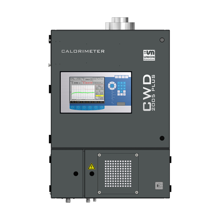
- Page 1 Users Manual CWD 2005 Combustion Calorimeter For high speed measurement of fuel gases...
- Page 2 Manual CWD 2005 Union Instruments GmbH Zeppelinstrasse 42 D 76185 Karlsruhe, Germany Phone : +49 721 – 95243 – 0 : +49 721 – 95243 – 33 Email : info@union-instruments.com : http://www.union-instruments.com Represented in China by: Anshan Union Industry and Commerce Company Ltd.
- Page 3 Manual CWD 2005 Attention: Please read all safety instructions before you connect the CWD 2005 See section 1.1 page 6 ___________________________________________________________________ Manual CWD2005.doc...
- Page 4 Manual CWD 2005 ___________________________________________________________________ Manual CWD2005.doc...
-
Page 5: Table Of Contents
Manual CWD 2005 Contents Important Information ................ 9 1.1. Safety Instructions ................10 Introduction ..................13 2.1. Output values .................. 13 2.2. Available measurement ranges ............14 2.3. Response times ................14 Analyzer Overview ................16 3.1. Dimensions, weights ............... 21 3.2. - Page 6 Manual CWD 2005 6.1.12. Keypad .................... 41 6.1.13. Menu Navigation ................41 6.2. Menu Overview ................42 6.2.1. Options .................... 44 6.2.1.1. Input/Output I/O ................45 6.2.1.1.1. Analog outputs ................45 6.2.1.1.2. Relay output ..................46 6.2.1.1.3. Display mA ..................47 6.2.1.1.4.
- Page 7 Manual CWD 2005 6.2.1.5.3. Dual Sample Streams ..............69 6.2.2. Trend Display .................. 70 6.2.2.1. Move cursor ..................71 6.2.2.2. Change time ..................71 . Change “y” values ................. 72 6.2.2.3. 6.2.2.4. Change signals ................73 6.2.2.5. Change units ................... 74 6.2.3.
- Page 8 Manual CWD 2005 11.1. Spare parts list ................100 11.2. Pressure regulators ............... 100 11.3. Low sample pressure ..............100 11.4. Gas conditioning ................100 11.5. Gas connections ................101 11.5.1. Adjust pressure regulator .............. 101 11.5.2. Calibration gas connection ............101 11.5.3.
-
Page 9: Important Information
Manual CWD 2005 Important Information Important Information Thank you for specifying a Union CWD 2005 Heating Value Analyzer for your online process measurement application. Please read this manual and follow all directions before installation and use of this gas analyzer. -
Page 10: Safety Instructions
Manual CWD 2005 1.1. Safety Instructions Before start up and use of the CWD 2005, please take time to carefully review this manual and its contents. Observe all Warnings, Cautions and Notes. Warning: Reasons to safe persons allow maintenance only after disconnect the main switch. - Page 11 The mixture will normally be similar to the major process gas components with a value around 80% of the analyzers range. CWD 2005 gas consumption is between 8 and 200 liters per hour and the quantity will depend on the characteristics of the process gas. When designing an outdoor shelter the use of a gas flow restrictor is recommended since it will limit the „potential...
- Page 12 Introduction Manual CWD 2005 ___________________________________________________________________ Manual CWD2005.doc...
-
Page 13: Introduction
5 minutes for the old mechanical water bath based units down to just a few seconds for the newly introduced CWD 2005 series. The CWD 2005 is the successor to the CWD 2000, CW95, CW85, CW71 and all previous models (about 10,000 units supplied) during more than 85 years service to the gas industry. -
Page 14: Available Measurement Ranges
Introduction Manual CWD 2005 provides a series of removable terminal strips where the 0-20 or 4-20 mA DC isolated outputs (proportional to the measuring range) and eight user programmable alarm contacts are available for customer connection. See section 10.2 for details. - Page 15 Manual CWD 2005 Analyzer Overview ___________________________________________________________________ Manual CWD2005.doc...
-
Page 16: Analyzer Overview
All major components are shown below and can be replaced if necessary as a spare part. Items marked with an * are not visible on this drawing – see following drawings. Figure 1: CWD 2005 components shown above but without doors for clarity ___________________________________________________________________... - Page 17 Manual CWD 2005 Analyzer Overview Output thermopile (mV Wobbe Index) Fixing screws thermopile PT 100 sensor temperature correction PT 100 sensor temp correction differential temperature PT 100 sensor temp correction differential temperature Cooling air orifice measurement „-“ Cooling air orifice measurement „+“...
- Page 18 Analyzer Overview Manual CWD 2005 Figure 2: Rear inside view of main door Power supply Port for connections Blower power supply Main Board ETX Board Blower ETX Board Keypad back side ___________________________________________________________________ Manual CWD2005.doc...
- Page 19 Manual CWD 2005 Analyzer Overview Figure 3: Front view 1 Cable gland signals Cable gland signals 3 Cable gland signals Cable gland signals PS M20 5 Cable gland ground M16 Filter cover 7 Switch on…off Door lock 9 Discharge Display...
- Page 20 Analyzer Overview Manual CWD 2005 Figure 4: Enclosure shown from left hand side Cable gland, signal Cable gland power Cable gland, signals Cable gland, signals Cable gland, signals USB Connection Interface connections Fast loop Carrier gas (SV.X11/3-4)* Calibration gas 2 (SV. X14/3-4)* Calibration gas (SV.X14/1-2)
-
Page 21: Dimensions, Weights
Manual CWD 2005 Analyzer Overview 3.1. Dimensions, weights Figure 5: Enclosure dimensions Height: 1020 mm 40.2 inches Width: 720 mm 28.3 inches Depth: 337 mm 13.2 inches Weight: 50.5 kg 111 lbs Protection: IP 54 NEMA 12 The analyzer is supplied for wall mounting, brackets are included. All gas connections are located on the left-hand side of the unit. -
Page 22: Gas Connections
Analyzer Overview Manual CWD 2005 3.2. Gas connections Gyrolok ¼” tube (6 mm) gas connections are located on the left hand side of the unit. The process and calibration gases should be connected separately. If a very short response time is required, a tube with a smaller diameter 1/8” (4 mm) can also be used, depending on sample gas but check that the pressure drop is not too large. - Page 23 Manual CWD 2005 Analyzer Overview Example 1: Wobbe jet Size: 0.55 S.G. Natural gas: 0.642 The Natural gas consumption corresponds to a range of Wobbe Index of: 14000 Wobbe (kcal/Nm³) or 60000 Wobbe (kj/Nm³) 18.1 liter/h In BTU and cubic feet 0 –...
-
Page 24: Electrical Power Supply
3.6. Ambient temperature limits The CWD 2005 should be installed in a room that does not exceed minimum and maximum temperature requirements. A typical temperature range is 10°C to 38°C (50 °F to 100°F). Higher (100°F or more) or lower temperatures will require cooling or heating. -
Page 25: Installation
Manual CWD 2005 Installation Installation Figure 6: Enclosure attachment / Exhaust Fixing element Cover insulation Draft brake Discharge CWD 2005 Fixing barcket The analyzer is intended to be mounted on the wall. 2 special fastening strips supplied from the manufacturer. They are equipped with 8 mm pins attached to the ___________________________________________________________________ Manual CWD2005.doc... - Page 26 Installation Manual CWD 2005 wall. On the back of the analyzer, there are holes in the struts affixed according to figure. A distance of 840mm must be available between the mounting strips (see Figure 7) to meet exactly the holes vertical distance on the back of the analyzer.
-
Page 27: Shelter Requirements
Manual CWD 2005 Installation 4.1. Shelter requirements The calorimeter shelter is subject to special conditions. How well these conditions are met is of extreme importance for the quality of the measurement. Room temperature changes must be slow. If necessary, only well controlled climate systems should be used. -
Page 28: Electrical Power Connection
Installation Manual CWD 2005 4.4. Electrical power connection The line power supply electrical connections are wired to the terminal block in the bottom section of the enclosure, see drawing figures 1 and 8. Check whether the available voltage supply matches the analyzers rated voltage. -
Page 29: Gas Connections
Manual CWD 2005 Installation 4.5. Gas connections All gas connections should be leak tested before use. Tube compression fittings are normally supplied and up to 5 gas connections are possible if all options including process gas, 2 calibration gases, carrier gas and fast loop are specified. -
Page 30: Pressure Regulators
The next unit is a primary regulator < 250 bars (3600 PSI) type GO PR1 has a 316 SS body and gauges. The outlet (2) pressure is adjustable from 0– 3.4 bar. A pre- pressure regulator is still necessary and acts as a second stage inlet pressure control for the CWD 2005. ___________________________________________________________________ Manual CWD2005.doc... -
Page 31: Sample Gas Pump
Manual CWD 2005 Installation Figure 12: High-pressure regulator GO PR1 < 250 bar (3600 PSI) Inlet ¼” (6 mm) Gyrolok tube Outlet ¼” (6 mm) Gyrolok tube Gauge high pressure Gauge, low pressure Pressure control wheel The last is a primary regulator < 250 bar (3600 PSI) with a 316 SS body and gauges adjustable outlet pressure from 0 –... -
Page 32: Carrier Gas Support
Installation Manual CWD 2005 sample gas inlet (see section 3.2). The pump must meet the requirements for flow and installation area classification. See Chapter 11 for more details. 4.5.4. Carrier gas Support Process gas with a high level of inert gas will not burn with a stable flame and these poor quality gases need a carrier gas support for combustion Typical carrier gases include Natural gas, Methane, LPG gas or Hydrogen. -
Page 33: Interfaces
4.6. Interfaces A range of electronic devices can be connected to the CWD 2005. The analyzer can be operated using a plug in mouse and a standard PC keyboard with PS2 connector. Figure 14: Interface connection on the left-hand side of the main door... - Page 34 Commissioning Manual CWD 2005 ___________________________________________________________________ Manual CWD2005.doc...
-
Page 35: Commissioning
Manual CWD 2005 Commissioning Commissioning When all electrical and gas connections have been completed and tested in accordance with all instructions, codes and regulations then the instrument is ready to be powered up. The following work must be carried out when commissioning the unit: Remove the transport tie wraps and transport screws from the specific gravity cell. - Page 36 Commissioning Manual CWD 2005 Remove the transport packing from the gas pressure regulator. Polystyrene foam is located beneath the removable regulator cover and must be removed before use. Check the process and calibration gas connections for tightness and correct connection. Check any carrier gas or second calibration gas connection if supplied.
- Page 37 Manual CWD 2005 Software ___________________________________________________________________ Manual CWD2005.doc...
-
Page 38: Software
Software Manual CWD 2005 Software Attention: This Manual is based on software release version 2.30. The Software consists of a number of menu levels, which can be accessed using the membrane keypad. All operations are similar and are entered via a series of interactive menus with user dialog boxes, system prompts and activity messages. -
Page 39: Menu Keypad
Stab. = signal stability value. During calibration the CWD 2005 determines the calibration duration based on current stability versus a pre-set stability value of < 0.15 to complete the calibration cycle and this level ensures that a stable calibration endpoint is reached. -
Page 40: Numeric Keypad
Software Manual CWD 2005 6.1.7. Numeric keypad For data input and escape from a menu (the “comma” key is the decimal point). 6.1.8. Burner window The burner provides heat to the thermocouples of the thermopile. The flame status uses a red LED, steady = flame ok, flashing = flame out. The system needs a stable symmetric blue flame for a stable measurement. -
Page 41: Keypad
Manual CWD 2005 Software 6.1.12. Keypad The keypad operator matrix is polled by the microprocessor once per second and pressing the button faster than one second will receive no system response. 6.1.13. Menu Navigation The block diagram shows three different shaped menu areas. The simple square areas indicate that there are more menu levels. -
Page 42: Menu Overview
Software Manual CWD 2005 6.2. Menu Overview 6.2.1.2. 6.2.1.3.7.2.1 6.2.2. Calibration Change Main Menu Trend language 6.2.1.3.7.2.2. 6.2.1.2.1. Bit maps 6.2.1. on /off Config. Options Selection calibr. gas 6.2.1.3.7.2.3. Transfer D: -> C: 6.2.1.2.2. 6.2.2. 6.2.1.3.7.2.4. 6.2.2.1. Automatic Trend Transfer Change time calibr. - Page 43 Manual CWD 2005 Software The Info field is right ahead on all screens. It shows actual information. Additionally actual measuring data are indicated which belong to the actual menu. In every individual screen different information are available. The description is made in the special section in this manual.
-
Page 44: Options
Software Manual CWD 2005 Fr = 42.01 controlled frequency of the fan 10. Stab=0.002 Stab = stability, standard deviation of the measured value average over 2 min.This information is important for a successful calibration. A typical value at the end of calibration is less than 0.015. Under this value calibration is finished. -
Page 45: Input/Output I/O
Manual CWD 2005 Software 6.2.1.1. Input/Output I/O Inputs and outputs can be linked together in any order. In the software, multiple identical outputs for a single measured value can also be programmed. For example: 3 outputs for Wobbe Index or 2 outputs for Specific Gravity etc. 3 remote contact inputs and 4 numeric screen displays are provided. -
Page 46: Relay Output
Software Manual CWD 2005 Signal is a multiple choice scrolling list field with the following text entries: Calorific Value; Wobbe, < Wobbe >, Specific Gravity, CV net <or gross>. Type is a list field with the following entries: 0 – 20 mA or 4 – 20 mA ”Unit”... -
Page 47: Display Ma
Manual CWD 2005 Software 6.2.1.1.3. Display mA This menu displays the mA output of each of the installed output modules in the information display. In the screen example, the first output is selected (using the “Display mA” key) and indicates 20 mA. Up to seven outputs can be installed. This feature can be helpful for output signal loop tests to remote equipment. -
Page 48: Display
Software Manual CWD 2005 Configuration example: On the connection board E/A external, the 3 remote digital contact inputs; Start measurement, Start calibration and Start hold are connected to terminal block number X3, on terminals 1 to 6. (See Chapter 10 for wiring details). -
Page 49: Calibration
Software 6.2.1.2. Calibration Calibration for CWD 2005: Calibration data is entered as Wobbe Index and Specific Gravity values. The standard analyzer will have one measuring range and will require one calibration gas. For a dual or three measuring ranges configuration, 1 or 2 calibration gases are required. -
Page 50: Configure Calibration Gas
Software Manual CWD 2005 6.2.1.2.1. Configure Calibration gas Calibration gas data is entered as a Wobbe Index and Specific Gravity number. If the gas vendor has only supplied the component % then the user must calculate and enter these three calibration gas values from the components of the calibration gas. -
Page 51: Calibrate
Manual CWD 2005 Software Day is a list field (Sun, Mon, Tue, etc.). Time and Cycle are value fields. Program 1: Calibration Monday at 15.00 hours. Program 2: Calibration every second workday at 12.00 hours. Program 3: Calibration every day at 23.00 hours. -
Page 52: Store Basic Calibration
Software Manual CWD 2005 6.2.1.2.4. Store Basic Calibration Store basic calibration stores the last calibration to get a fix point for the calibrations. The point is important to see the deviation at the next calibration and to have a deviation limit for a signal if the limit hits a programmed limit. -
Page 53: System
Manual CWD 2005 Software 6.2.1.3. System This menu item contains the following basic analyzer configuration parameters.Two pages open the different items of the menu. The button swiches from one page to the other page. The next line with other three menus. -
Page 54: General
Software Manual CWD 2005 6.2.1.3.1. General Change signal after hold provides in a soft transition to and from the calibration cycle or when switching off the output signal hold module. This prevents a sudden rise or fall in the measured value occurring in output signal. The transition between values is shown in seconds and this allows the signals to blend together for a smooth transfer. -
Page 55: Ignition
6.2.1.3.3. Update If a new update is required, a CWD 2005 software memory stick has to be inserted in the left side of the door. Start by pressing the “Update” menu key and the update starts automatically. -
Page 56: Load Factory Configuration
Software Manual CWD 2005 6.2.1.3.4. Load factory configuration “Load factory configuration” loads the standard data input as supplied by the factory or installed at the last service. If the customer has changed several menu items and problems arise because of malfunction with the instrument, this key allows a return to factory default by running the standard configuration as supplied by the factory Note: Without a memory stick in the slot an error message appears “Unable to open... -
Page 57: Settings
Manual CWD 2005 Software 6.2.1.3.7. Settings Settings are all menu buttons which belong to basic configuration and are only seldom or only from time to time used 6.2.1.3.7.1. Time/Date Set the system time and date, the clock stops when the menu is open. Use CANCEL to exit the menu without making any changes. -
Page 58: Language
Software Manual CWD 2005 6.2.1.3.7.2. Language The menu language consists of 10 submenus. With the button all the menus can be reached. After the first 4 menus the next 4 menus appear and at least the last 2 ones. ___________________________________________________________________... -
Page 59: Change Language
Manual CWD 2005 Software 6.2.1.3.7.2.1. Change language The analyzer has German and English display capability. Other languages can be included relatively easily. A TXT file is available for translation by a customer from one language (English) into another and requires ~ 1100 words. -
Page 60: Transfer W. D:>C
Software Manual CWD 2005 6.2.1.3.7.2.3. Transfer W. D:>C: This key starts the copy of the dictionary (LANGUAGE files) from the memory stick D to the hard disk C of the unit 6.2.1.3.7.2.4. Transfer W. C:>D: This button starts the copy of the complete dictionary in english and german language (Standard) from C to the memory stick. -
Page 61: Change Usb
Manual CWD 2005 Software 6.2.1.3.7.2.10. Change USB The USB port is also available for a floppy disc. The switch can be made here. 6.2.1.3.7.3. Password A password can be selected if required by the user. If selected, no system changes can be made without entering the pass-code. -
Page 62: Color Settings
Software Manual CWD 2005 6.2.1.3.7.4. Color Settings 6.2.1.3.7.5. Hardware 1 This menu contains data parameters for dual range and carrier gas options. The amount of dual range overlap can be selected. Burner time constant, Wobbe jet and range conf. are specific to the burner type, range and configuration. These parameters are application specific and it is strongly recommended that changes in this table should not be made without consultation with the factory. - Page 63 Manual CWD 2005 Software Range Cfg. Code (binary) for measuring status during a range change. Range not selected or displayed. Wobbe jet set 2 or jet set 1. Combustion air jet on or off. Carrier gas (combustible gas) on or off.
-
Page 64: Service
Software Manual CWD 2005 6.2.1.4. Service User access to the service menu is not required for normal operation as all the user menus and controls are located outside of this area. The screen shot above shows a sample of the menu beyond the password-protected area. -
Page 65: Customer Specific Application
Manual CWD 2005 Software 6.2.1.5. Customer specific application Several different menus described below. These options are pre-programmed by the factory as required. Restart power to the unit after an option is selected to enable it. ___________________________________________________________________ Manual CWD2005.doc... -
Page 66: Air Conditioning Room Temperature
Software Manual CWD 2005 6.2.1.5.1. Air conditioning room temperature A PID controller is available as an option for use with variable room temperatures and can control high and low room temperatures. The parameters are programmed at the factory only change parameters after consultation with the manufacturer. - Page 67 Manual CWD 2005 Software The “Cut paper“ command cuts the printer paper. During the procedure any data is stored and printed afterwards. The service LED on the screen flashes as a warning to change the printer roll. During this procedure any data is stored and printed afterwards.
- Page 68 Software Manual CWD 2005 “Time interval“select the print time in minutes. This is an average of the time interval and the minimum and maximum value of this interval is also displayed. The daily value gives an average over one day. The example prints out at midnight.
-
Page 69: Dual Sample Streams
Note: A small dual stream sample module with gauges, regulators and filters, including a calibration gas connection is available as an option. This module can be wall mounted near the CWD 2005 gas inlet connections. The following screen shows a typical dual sample stream trend with 10 minutes on each sample stream with process gas 1 currently online. -
Page 70: Trend Display
Manual CWD 2005 6.2.2. Trend Display The CWD 2005 has a very powerful trend capability that can be plotted on the screen in user configurable time scales and in different units of measurement including Calorific Value, Wobbe Index, and Specific Gravity and others. -
Page 71: Move Cursor
Manual CWD 2005 Software 6.2.2.1. Move cursor With the Button the selection of the three info windows is done. To change the selected line and choose the different physical values the arrows and the return in the circle are active points . -
Page 72: Change "Y" Values
Software Manual CWD 2005 Every touch of the button makes one step. The meaning of the symbols are: Value linear right x axis Value linear left 25% x axis Value pressed x axis Value stretched x axis . Change “y” values 6.2.2.3. -
Page 73: Change Signals
Manual CWD 2005 Software Value linear up y axis Value linear down y axis Value pressed y axis Value stretched y axis Now the specific gravity window is selected. The three lines Dif y delta from line to line 15,00... -
Page 74: Change Units
Software Manual CWD 2005 6.2.2.5. Change units The handling of the menu change signals is the same as before described. Note: The trend data is the only data that will be erased if power is lost to the instrument. ___________________________________________________________________... -
Page 75: Event List
“Status calibration” gives deviation from the last calibration in % with date and time. During an update of the CWD 2005 sometimes a message can appear „ADU error“. This message is also shown in the event list. This message is not a real error. It is only an indication that the AD converter is recalibrated. -
Page 76: Device Info
Software Manual CWD 2005 6.2.4. Device Info This Info Menu shows all important data of each instrument. In case of questions or trouble please give these data to the manufacturer. Every change in the screens which are important for the running is automatically stored in this screen device Data. - Page 77 Manual CWD 2005 Maintenance ___________________________________________________________________ Manual CWD2005.doc...
-
Page 78: Maintenance
Maintenance Manual CWD 2005 Maintenance 7.1. Safety instructions for maintenance or repair Use the main power switch to remove power for maintenance and other work. Caution: The burner, ignition electrode and the heat exchanger can be very hot. Do not jump out any switches or safety devices. -
Page 79: Replacement I/O Boards
Manual CWD 2005 Maintenance 7.4. Replacement I/O Boards If a replacement board E/A internal or E/A external becomes necessary, special updated software is required ( delivered with the new board). Boards of old style and new style are similar and exchangeable (for more details, see section 10.2.). -
Page 80: Troubleshooting
Troubleshooting Manual CWD 2005 Troubleshooting Troubleshooting section is broken down into various topics such as unstable readings, drift in readings and incomplete ignition. The following list describes typical faults and corrective actions. This list will be updated in the future as the need arises. -
Page 81: Incomplete Ignition
The memory stick contains six different program routines, which can be executed in the CWD 2005 drive and are explained in the following text. The memory stick must be removed after the completion of the selected program and the unit has to be rebooted. - Page 82 Troubleshooting Manual CWD 2005 Note: After several minutes of loading files the screen will return to the start menu with the six vertical arrows, power down the unit, remove memory stick and restore power. The unit will now run through the normal short start-up routine.
- Page 83 This program generates the calibration data of the EA-extern board when that is replaced in a CWD 2005 system with a new one. The new data file is provided and delivered with the board by the manufacturer. An operation error is impossible because the memory stick supplied in this case only executes program 4.
-
Page 84: Measurement Principle
Manual CWD 2005 Measurement principle The measurement of process gases by the CWD 2005 is based on a thermopile principle that has been proven over many years in every type of industry. The thermopile used is of unique construction and the use of a high-speed thermopile... -
Page 85: Thermopile Measuring System
Manual CWD 2005 Measurement principle measuring principle described below. independent physical measurements are carried out. These are Wobbe Index value and Specific Gravity and the computer calculates the Calorific Value using following formula: Calorific value Wobbe Index Specific Gravity 9.2. - Page 86 Measurement principle Manual CWD 2005 a differential voltage (6) at the thermopile that is independent of the cooling air temperature. Broadly speaking this is proportional to the Wobbe Index of the gas. Airflow (3) and gas flow (7) must be regulated very accurately. The gas flow is regulated to a constant level by an extremely precise, weighted gas pressure regulator (8).
-
Page 87: Specific Gravity Measuring Cell
Measurement principle 9.2.1. Specific Gravity measuring cell The CWD 2005 (The W 2005 is supplied without the Specific Gravity cell) is fitted with a specific gravity measurement cell, which is mounted in the enclosure. The specific gravity cell determines the specific gravity of the process gas in a specially designed sample chamber in the presence of a modulated acoustical field. -
Page 88: Functional Diagram
Measurement principle Manual CWD 2005 9.2.3. Functional diagram Figure 19: Functional diagram of the Specific Gravity measuring cell 9.2.4. Output signals The standard measuring range is 0.2 – 2,2 Specific Gravity (Air = 1.0) The output signal for the measuring cell is expressed as: U 0 - 5 Volt Specific.Gravity... -
Page 89: Testing And Calibration
Manual CWD 2005 Measurement principle 9.2.6. Testing and calibration Specific gravity cell function can be tested using 2 gases. The specific gravity of the two gases should differ by more than 0.5 so that the zero and span can be checked. -
Page 90: Circuit Diagrams
Circuit diagrams Manual CWD 2005 Circuit diagrams The following circuit diagrams show only the major components. Component level drawings are only supplied under special confidentiality terms and conditions. 10.1. Input-Output card: E/A internal D9 D10 D11D12 D2 D7 D21 D22 CW2000EAintern-07_2007_02_26 Figure 21: Input/output card E/A internal showing module/plug positions. - Page 91 Manual CWD 2005 Circuit diagrams Plug X10 Pin 1 +24V VI Thermal switch Pin 2 -24 V VIS Thermal switch Plug x14 Pin 1 Solenoid valve calibration gas I Pin 2 +24V Solenoid valve calibration gas I Pin 3 Solenoid valve calibration gas II...
- Page 92 Circuit diagrams Manual CWD 2005 Plug x 3 Pin 1 PT6+ No Connection Pin 2 PT6- No connection Pin 3 PE Screen Pin 4 N.C.. Pin 5 N.C. Pin 6 N.C. Plug x 7 No Connection Pin 1 No Connection...
-
Page 93: Input-Output Card E/A External
Manual CWD 2005 Circuit diagrams 10.2. Input-Output Card E/A external The user electrical connections have the following technical dimensions: Connections: Conductor cross section solid 0.14 mm² - 1.5 mm² Conductor cross section stranded 0.14 mm² - 1.5 mm² stripping length: 7 mm 10.2.1. -
Page 94: Relay Outputs
Circuit diagrams Manual CWD 2005 10.2.1.1. Relay outputs The relay outputs are connected to terminal block X14. The relay contacts have the following specifications Maximum current: 1amp max. 100 Volt, 100V DC/30Watt, 100V AC/60VA If the relay is operational, a red alarm LED is illuminated. -
Page 95: Analog Outputs
Manual CWD 2005 Circuit diagrams 10.2.1.2. Analog outputs The mA outputs are connected to terminal block X 5 The maximum loop resistance for the mA outputs is 500 Ohms with signal isolation. If more than three current outputs are required, additional DC/DC isolation modules will be required for each output. -
Page 96: Digital/ Relay Contact Inputs
Circuit diagrams Manual CWD 2005 10.2.1.3. Digital/ Relay contact inputs The digital control inputs are connected to terminal block X 3 All digital control inputs are protected by internal opto-isolators. If the control input in question is connected, a LED will display its status. -
Page 97: Open Collector Drives Or Ma Outputs
Manual CWD 2005 Circuit diagrams 10.2.1.4. Open collector drives or mA outputs Warning: To avoid possible damage to the output circuit, please ensure that the open collector output is connected correctly. OC = Open Collector output Rel. = Relay output mA = mA output Output. -
Page 98: Serial Interface Rs232 (Option)
Circuit diagrams Manual CWD 2005 10.2.1.5. Serial interface RS232 (Option) The RS232 interface can be used to transmit measured values to a remote location. Parameter selection is made in the menu “I/O Analog outputs”. The RS232 interface is connected to block X 11 and to block X 1. -
Page 99: Profibus-Dp Interface
10.2.1.6. Profibus-DP Interface The CWD 2005 can be supplied with several bus-interfaces. The system provides float Data in Intel Type and Byte Data. They can be connected to the fieldbus at the serial interface. The binary data in Intel Format must be interpreted by the customer. -
Page 100: Appendices
Appendices Manual CWD 2005 Appendices 11.1. Spare parts list A list of recommended spareparts for 1 year and 2-3 years operation can be found in chapter 7 under the heading Consumables. If any unusual conditions are inspected at the job site, the factory can offer advice, so that specially selected spare parts packs can be provided. -
Page 101: Gas Connections
18 mbar and a pressure gauge range 0 - 25” H O (0-60 mbar). The gauge in front of the CWD 2005 is necessary to show inlet pressure level. Calibration gas is clean and a filter is not necessary. -
Page 102: Process Gas Connection
9). The use of a pressure gauge 0-25 “H O (0–60 mbar) is recommended between the pre regulator and the input of the CWD 2005. Steel industry gases such as BF gas or Coke gas need a larger filter (see section 4.5.1 fig.10) and a mounting plate complete with a filter and bypass valves is an... - Page 103 Manual CWD 2005 Appendices Figure 25: Process Gas line (maximum pressure 60 bar) Process gas supply line High-pressure regulator Sample gas filter Pre regulator (Zn) 6/18mbar. Pressure gauge 0-60 mbar CWD 2005 Figure 26: Process Gas line (maximum pressure 60 bar) High-pressure regulator 60 bars –...
-
Page 104: Double Range
If an extended range is necessary (for example 20-100 %) it can´t be done with one jet combination of Wobbe jet and air jet. For this purpose the CWD 2005 will be equipped with a double orifice for 2 wobbe-jets and 2 air-jets. .The jet-change will be made with 4 solenoid valves automatically. -
Page 105: Carrier Gas
Manual CWD 2005 Appendices 11.7. Carrier Gas When a carrier gas is necessary both combustible and non combustible gases can be suitable for carrier gas, depending on process gas used in the application. Normally blast furnace gas with a low content of CO and H needs a carrier gas option. -
Page 106: Fast Loop
11.8. Fast loop The CWD 2005 itself has a high-speed response time but the installed response speed depends on the volume of the process connections with regulators and filters. To calculate the volume of the tube with the volume of filters and regulators, see Chap. -
Page 107: Air Consumption With Co Measurement
Variable content of CO needs an additional measurement of CO. this is the only way to reach exact values of air consumption. It is possible to install a CO-module in the CWD 2005. The module is delivered separately and has to be installed before the instrument is started. The CO measuring cuvette is sensitive and could possibly be damaged if it was installed during transportation. - Page 108 Appendices Manual CWD 2005 Figure 30 CO-Module installed in the CWD 2005 CO Measuring cuvette Gas inlet CO Module Gas outlet Gas inlet and gas outlet to the module may be inverted. There is no flow direction dictated. ___________________________________________________________________ Manual CWD2005.doc...
- Page 109 Manual CWD 2005 Spare parts ___________________________________________________________________ Manual CWD2005.doc...
-
Page 110: Spare Parts
Spare parts Manual CWD 2005 Spare parts 12.1. Spares electronics Specific Gravity Sensor - heated - +/-15V / 7VA - Range 0,2 – 2,2 dv LFE 209C Specific Gravity Sensor - heated - +/-15V / 7VA - Range 0,0 – 2,0 dv... -
Page 111: Spares Electric
110 resp. 190 VAC Weight: 6000 gram Order description: Fan CWD 2000/2005, type RDO 110 resp. 190 VAC Order number: 02402199988 Fan CWD 2005, type 24 V DC Weight: 2300 gram Order description: Fan CWD 2005, type24V DC Order number: ___________________________________________________________________... - Page 112 Spare parts Manual CWD 2005 Ignition transformer TZI5/100W, 230V/50Hz with ignition lead and plug Weight: 1600 gram Order description: Ignition transformer TZI5/100W, 230V/50Hz Order number: 02402199985 Ignition transformer TZI5/100N, 115V/50(60)Hz with ignition lead and plug Weight: 1600 gram Order description:...
- Page 113 Manual CWD 2005 Spare parts plug-in relay 110 V series 40.31 with 1 changer Weight: 17gram Order description: plug-in relay 110 V series 40.31 with 1 changer Order number: 98402199993 plug-in relay 230 V series 40.31 with 1 changer Weight: 20 gram Order description: plug-in relay 230 V series 40.31 with 1 changer...
-
Page 114: Spares Gas
Weight: 365 gram Order description: Solenoid valve CWD 2000/2005 Order number: 02402199996 Precision gas regulator Compatible to Union instruments CWD2005 Pin max. 50 mbar, Pout 4 mbar Weight: 950 gram Order description: Precision gas regulator to type CWD2005 Order number: ___________________________________________________________________ Manual CWD2005.doc... - Page 115 Manual CWD 2005 Spare parts Diaphragm for precision gas regulator - D = 96 mm - Material NBR Weight: 10 gram Order description: Diaphragm to precision gas regulator Order number: CWXX-S-G-PRECDIA Neoprene tube 6 x 2 mm, black, 6 mm...
-
Page 116: Spares Measurement System
Spare parts Manual CWD 2005 12.4. Spares measurement system Thermopile with 24 thermoelemnts, diameter=1,0mm Weight: 700 gram Order description: Thermopile with 24 thermo elements, diameter=1,0mm Order number: 02403199997 Heat exchanger 0,2mm with clamp collar Weight: 60 gram Order description: Heat exchanger 0,2mm with clamp collar... - Page 117 Manual CWD 2005 Spare parts Orifice gas or air - Material alu / Perbunan NBR - Diameter x.xx mm Weight: 5 gram Order description: Orifice Order number: cw05-s-m-origas x.xx mm Orifice gas or air - Material alu / Perbunan NBR - Diameter x.xx mm...
-
Page 118: Spares Burner
Spare parts Manual CWD 2005 12.5. Spares burner Burner Type H with 9 quarz-jets to CWD2000/2005 - Material Aluminium-Stainless Steel Weight: 125 gram Order description: Burner Type H complete (Mat. Alu./SS) to CWD2000/2005 Order number: cw00-s-b-hcalss Single quarz-jet with threaded sleeve... - Page 119 Manual CWD 2005 Spare parts Burner type LM for low BTU gas with Aluminium head for CWD 2000/2005 - Material Aluminium-SS316 - Burner head 36 holes diameter 1,9 mm Weight: 115 gram Order description: Burner LM for low BTU gas with ALU-head for CWD2000/2005...
-
Page 120: Spares Air
Spare parts Manual CWD 2005 12.6. Spares air Air filter for CWD2000/2005 - 200 x 200 x 95 mm Weight: 510 gram Order description: Air filter for CWD2000/2005, 200 x 200 x 95 mm Order number: 02401199996 12.7. Spares enclosure... -
Page 121: Technical Data
Manual CWD 2005 Technical Data Technical Data Technical Data System CWD 2005: Process computer: PC104, 486, 66MHz, 8MB disk on chip flash memory. Real time processing system with multi-tasking ability Measuring Range: 40 to 100% F.S. Dual Range: 20 to 100% F.S.
Need help?
Do you have a question about the CWD 2005 and is the answer not in the manual?
Questions and answers