Table of Contents
Advertisement
Advertisement
Chapters
Table of Contents

Related Manuals for Zeiss SL 120


Summary of Contents for Zeiss SL 120
- Page 1 SL 120 Slit lamp Documentation set...
- Page 2 It does not, however, continuously check for any changes which could form the basis for liability. If Carl Zeiss Meditec AG determines that a link which it has incorporated could result in civil or criminal liability, or is alerted to the fact by a third party, the link will be removed.
- Page 3 Contents User manual SL 120 Slit lamp [000000-1490-499-GA-GB-090118] 000000-1490-499-Inhalt0-GB-090118...
- Page 5 SL 120 Slit lamp User manual...
- Page 6 000000-1490-499-GA-GB-090118...
-
Page 7: Table Of Contents
Description of the instrument ..........16 Installation ................20 Notes on installation and use ............... 20 Unpacking ..................... 21 Assembly of the SL 120 Slit Lamp ..............22 Electrical connection ..................24 Power supply unit ..................... 24 Daily use ................... 25 Switching on .................... - Page 8 Contents Shutting down ................. 33 Switching off the instrument ............... 33 Maintenance and care ............. 34 Replacing the lamp ..................35 Maintenance ....................36 Care and cleaning .....................36 Safety inspections ..................37 Optional accessories ..............38 Mounting the beam splitter ................. 39 Mounting a filter changer with barrier filter (yellow) ........
-
Page 9: Notes On The User Manual
Correct operation of the system is imperative for its safe and successful functioning. You should therefore ensure that you are thoroughly familiar with this user manual before setting up and using the SL 120 Slit Lamp for the first time. -
Page 10: Explanation Of Symbols Used
Notes on the user manual Explanation of symbols used The symbols used in this user manual refer to important safety information which may warn against possible health risks or fatal injuries and contain useful notes. Whenever you see these symbols, read the accompanying information carefully and observe all safety notes and information in this user manual and on instrument labels. -
Page 11: Package Check List
Package check list Package check list The following components are included in the delivery scope: • SL 120 Slit Lamp • Halogen bulb • Eyepieces • Dust cover • Power supply unit • Power cable • Documentation set 000000-1490-499-GA-GB-090118... -
Page 12: Country-Specific Information And Labels
Country-specific information and labels Country-specific information and labels Classification/Manufacturer's declaration WARNING - GENERAL HAZARDS This device may only be set up, operated and used for the specified purpose and according to national regulations, applicable industry standards and occupational safety and accident prevention regulations. Further notes on classification are to be found in section Technical data, page 49 and following. -
Page 13: Intended Use
Responsibility for using the device other than as intended lies with the user. CAUTION - RISKS ARISING FROM OPERATING ERRORS Do not use the SL 120 Slit Lamp in patients with the following conditions: • Unable to follow the instructions of the user •... -
Page 14: Intended User Profile
Please also adhere to the national qualification guidelines applicable in your country. Persons who operate the SL 120 Slit Lamp must have completed the following training: • Ophthalmologist •... -
Page 15: Disposal Of The Product
Country-specific information and labels Disposal of the product CAUTION - RISK OF ENVIRONMENTAL POLLUTION Packaging materials should be retained for future relocation or repair. If you decide to dispose of the packaging material, submit it to a recognized collection system for recycling. The device contains electronic components. -
Page 16: External Labels
Country-specific information and labels External labels Fig. 1 Labeling of the SL 120 Slit Lamp 000000-1490-499-GA-GB-090118... -
Page 17: Fig. 2 Labeling Of The Power Supply Unit
Country-specific information and labels Fig. 2 Labeling of the power supply unit 000000-1490-499-GA-GB-090118... - Page 18 EU conformity symbol Disposal advise for EU Not applicable Not applicable Identification sign for the focusing rod as accessory of SL 120 Slit Lamp Power supply unit type label EU conformity symbol NRTL approval for USA and Canada Application part type B...
- Page 19 Country-specific information and labels Item Label Explanation Information label "Disconnect device from the power supply before opening" Information label "Observe user manual" 000000-1490-499-GA-GB-090118...
-
Page 20: Performance Specifications
Additional optical elements such as contact or correction lenses also render the deeper regions of the eye and the chamber angle visible. The SL 120 Slit Lamp is designed for the complete application area of a typical slit lamp. It is used by ophthalmologists, optometrists and opticians. -
Page 21: Service Life
Performance specifications Service life WARNING - GENERAL HAZARDS The development, production and maintenance of this device, together with associated risks, are based on an expected service life of eight years, assuming that the device is serviced at the specified intervals. Modifications to the product or failure to follow the manufacturer’s instructions may substantially reduce the expected service life and significantly increase the risks associated with the use of this device. -
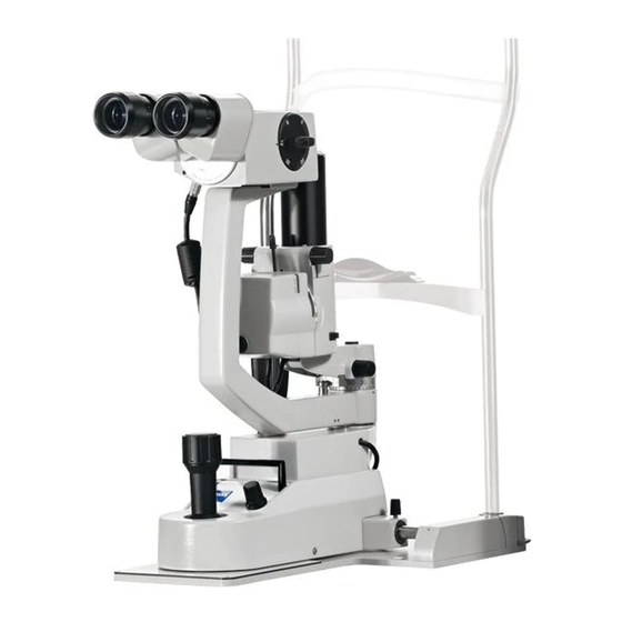
Page 22: Description Of The Instrument
Description of the instrument 1 Stereo microscope comprising five-step magnification changer and binocular tube (optionally convergent or parallel tube) 2 Slit projector with lamp housing 3 Head rest 4 Instrument base Fig. 3 Structure of the SL 120 Slit Lamp 000000-1490-499-GA-GB-090118... -
Page 23: Fig. 4 Controls Of The Stereomicroscope
Description of the instrument 1 Hexagon socket screw for fastening the binocular tube or the accessories for observation or documentation 2 Mounting plane for accessories 3 Stereomicroscope 4 Galilean magnification changer, 5-steps Magnifications of 5/8/12/20 and 32x (in combination with 10x eyepiece). The set value is facing the operator. -
Page 24: Fig. 5 Controls Of The Slit Projector
Description of the instrument 1 Lamp housing 2 Slit width control, 0 mm to 14 mm, continuously adjustable, marks at 0.3/1/2 mm 3 Decentering controls for retroillumination 4 Diffusor for diffuse illumination, can be flipped up onto the prism head. 5 Scale for horizontally inclined illumination (only in version with tiltable prism head) 6 Knurled control for setting 0°... -
Page 25: Fig. 6 Controls Of Instrument Base With Head Rest
Description of the instrument 1 3D joystick control for lateral and height adjustment (the latter by turning the control) 2 Quick-action lock 3 Fixation lamp mounting (right figure shown with cover cap) 4 Forehead rest 5 Red eye level marks (to identify the patient eye level needed for optimum observation) 6 Fastening pins for paper pads 7 Chin rest 8 Hole for mounting the focusing rod... -
Page 26: Installation
6A type B. Installation of the device with a power supply unit which has not been approved by Carl Zeiss Meditec must conform to IEC 60601-1 or relevant national requirements. Responsibility for the electrical safety of the device, including its electromagnetic compatibility (EMC), lies then exclusively with the user. -
Page 27: Unpacking
Installation CAUTION - PROPERTY DAMAGE Do not store or use this device in damp rooms. Do not expose the device to water splashes, dripping or sprayed water. CAUTION - PROPERTY DAMAGE Handle with care; the instrument should not be lifted or carried by the base plate. -
Page 28: Assembly Of The Sl 120 Slit Lamp
Installation Assembly of the SL 120 Slit Lamp CAUTION - DANGER FROM FALLING PARTS When selecting a suitable table, ensure that the combination of table and instrument is stable up to an angle of tilt of 10°. Furthermore, the table must be designed for 4 times the weight of the device configuration. -
Page 29: Fig. 7 Assembly Of The Sl 120 Slit Lamp
Installation Screw holes to fix the device on the instrument table Fastening screws Plastic caps Eyepieces Binocular tube Hexagon socket screw on the stereomicroscope Fig. 7 Assembly of the SL 120 Slit Lamp 000000-1490-499-GA-GB-090118... -
Page 30: Electrical Connection
Installation Electrical connection Power supply unit 1 Power switch 2 Fastening plate with four threaded holes Fig. 8 Front of power supply unit Connector for slit illumination cable Connectors for fixation lamp and DigiCam Illuminator Power supply Fig. 9 Rear of power supply unit CAUTION - PROPERTY DAMAGE You may use only a power cable with straight appliance socket. -
Page 31: Daily Use
If using a table not approved by Carl Zeiss Meditec, the user is solely responsible for ensuring the electrical safety of the instrument. Switching on Switch on the SL 120 Slit Lamp using the power switch (1, Fig. 8) on the power supply unit. 000000-1490-499-GA-GB-090118... -
Page 32: Operation Of The Instrument
Operation of the instrument Operation of the instrument WARNING - RISK OF OPTICAL RADIATION This is a group 2 device according to ISO 15004-2:2007. The light emitted by this device may be harmful. The risk of eye damage increases with the length of exposure to rays. Exposure at maximum intensity for more than 4.9 min will exceed the hazard reference value. - Page 33 CAUTION - RISK OF PINCHING On the SL 120 Slit Lamp various mechanical units can be moved relative to each other. Avoid trapping your fingers between them. 000000-1490-499-GA-GB-090118...
-
Page 34: Preparations
Operation of the instrument Preparations Slit lamp • Set interpupillary distance of binocular tube. • Adjust the eyepieces: If you wear glasses, push the eyecups in and set the diopter setting ring to 0 D. Other operators should pull the eyecups out and set their refractive powers at the diopter scale of the eyepieces. -
Page 35: Setting The Slit Brightness
Operation of the instrument Setting the slit brightness • Switch the device on at the power switch (1, Fig. 8) of the power supply unit. • Then turn the brightness control (7, Fig. 11) on the instrument base to the desired brightness. In the left final position of the control there is no power supplied to the lamp. -
Page 36: Fig. 11 Adjust The Slit Lamp
Operation of the instrument 1 3D joystick control for lateral and height adjustment (the latter by turning the control) 2 Filter setting wheel (with green filter (red-free), free aperture and blue filter) 3 Red eye level marks (to identify the patient eye level needed for optimum measurement) 4 Chin rest 5 Decentering controls for retroillumination 6 Red mark indicating the mid-position of the height adjusting range... -
Page 37: Adjusting The Illumination
Operation of the instrument Adjusting the illumination The light dose is based on the illuminance and exposure time. Very long exposure times of the same area of the retina are not typical, as slit lamp examination is a dynamic process. The illuminance directed on the fundus can be reduced as follows: •... -
Page 38: Gonioscopy
Operation of the instrument Gonioscopy Fig. 12 Adjusting the illumination angle on the prism head • Contact glasses must be disinfected and undamaged. • For gonioscopy, the three-mirror contact glass is used. • To cover different angular ranges, the illumination angle can be varied relative to the horizontal between 0°... -
Page 39: Shutting Down
• Penetration of substances • Faults that cannot by remedied according to the descriptions in this user manual Switching off the instrument Switch off the SL 120 Slit Lamp using the power switch (1, Fig. 8) on the power supply unit. 000000-1490-499-GA-GB-090118... -
Page 40: Maintenance And Care
Such actions will also render any warranty claims invalid. WARNING - RISK OF ELECTRIC SHOCK The user may only open the SL 120 Slit Lamp in order to replace the bulb. Any other action involving access to the interior of the instrument may endanger both operator and patient. -
Page 41: Replacing The Lamp
Maintenance and care Replacing the lamp CAUTION - RISK OF BURNS Before replacing the lamp, switch the instrument off and disconnect the power cable. Allow the lamp to cool down or wear protective gloves. Lamp holder Lamp (6 V/20 W halogen) Spring-loaded catch Knurled screw Fig. -
Page 42: Maintenance
Maintenance and care • Slide lamp holder (1, Fig. 13) onto the contact pins of the bulb (2, Fig. 13). • Let the catch (3, Fig. 13) engage again. • Finally, attach the cover to the lamp housing and fix it by means of the knurled screw (4, Fig. -
Page 43: Safety Inspections
Maintenance and care • Due to its simple and compact construction, the SL 120 Slit Lamp is almost maintenance-free. It is, however, necessary to clean the optical components (objective, eyepiece) occasionally. To remove dust from surfaces accessible from the exterior, use a soft brush. -
Page 44: Optional Accessories
Optional accessories Optional accessories WARNING - RISK OF OPTICAL RADIATION Use only accessories and spare parts approved by Carl Zeiss Meditec. • Beam splitter (see DigiCam Set user manual) • Filter changer with barrier filter (yellow) • ACCENTO Ergotube (because of spacing issues only to be used together with other accessories) •... -
Page 45: Mounting The Beam Splitter
Optional accessories Mounting the beam splitter 1 Left port for beam splitter 2 Hexagon-socket screw on the beam splitter 3 Prism slide 4 Hexagon socket screw on the stereomicroscope 5 Right port for beam splitter Fig. 14 Mounting the beam splitter •... -
Page 46: Mounting A Filter Changer With Barrier Filter (Yellow)
Optional accessories Mounting a filter changer with barrier filter (yellow) Fig. 15 Filter changer with barrier filter (yellow) You can swing the yellow filter into the light path by means of the lever shown beside. The filter serves as barrier filter for the work with fluorescein and with a blue filter in the observation path. -
Page 47: Mounting The Accento Ergotube
Optional accessories Mounting the ACCENTO Ergotube Fig. 16 ACCENTO Ergotube The ACCENTO Ergotube causes the convergent or parallel tube to slant upwards by 15°, relieving strain on the neck when working. Mount the ACCENTO Ergotube, like the beam splitter (Fig. 14), between optional accessories (beam splitter, compact video attachment , filter changer with barrier filter (yellow)) and binocular tube by means of hexagon socket screws. -
Page 48: Digicam Adapter
Optional accessories DigiCam Adapter Fig. 17 DigiCam Adapter The DigiCam Adapter allows standard digital cameras to be connected for the purpose of photographic documentation. You can find notes on mounting and operating the Digicam Adapter in the DigiCam Set user manual. 000000-1490-499-GA-GB-090118... -
Page 49: Digicam Illuminator
Optional accessories DigiCam Illuminator Fig. 18 DigiCam Illuminator The DigiCam Illuminator is a separate illumination system for illuminating the area surrounding the projected slit for the purpose of photographic or video documentation. You can find notes on mounting and operating the Digicam Illuminator in the DigiCam Set user manual. -
Page 50: Focusing Rod
Optional accessories Focusing rod Fig. 19 Focusing rod The focusing rod can be installed in hole (8, Fig. 6). The focusing rod can be used for determining the individual diopter setting on the eyepieces to compensate for ametropia of the observer or possible instrument myopia. The exact adjustment of the eyepieces is a prerequisite for good examination results and is necessary when using a video or photographic camera on a slit lamp or when using the slit lamp as laser slit lamp. -
Page 51: Fixation Lamp
Optional accessories Fixation lamp Cover Lamp/diode Sleeve nut to clamp the fixation lamp to the head rest Fig. 20 Fixation lamp The fixation lamp is the lamp on which the non-examined eye of the patient can be fixed. A plug-in socket (3, Fig. 6) with electrical contact has been provided on the head rest for mounting and power supply to the fixation lamp (see Fig. -
Page 52: Special Eyepieces
Optional accessories Special eyepieces 12.5x eyepieces and a 10x micrometer eyepiece with linear and angular scales are available. 10x micrometer eyepiece with linear and angular scales Fig. 21 10x micrometer eyepiece with linear and angular scales This eyepiece has a linear scale of 15 mm length graduated to 0.2 mm. Use of this eyepiece requires the 8x position of the magnification changer. -
Page 53: Angular Measurement
Optional accessories The special eyepiece has an angular scale of 180° graduated to 2° for the measurement of the inclination angle. A gravity ball (1, Fig. 22) produces the artificial horizon required for the angular measurement. Angular measurement Gravity ball Measuring edge Fig. -
Page 54: Breathing Shield
Optional accessories Breathing shield • The breathing shield may be mounted to the stereomicroscope to protect the patient and physician from each other's breath. Paper pads • They improve hygienic conditions. Fender plate Fig. 23 Fender plate The fender plate is used to prevent collision of slit lamp and headrest, when the slit lamp is mounted to instrument setups. -
Page 55: Technical Data
Technical data Technical data Rated voltage 100 V - 10 % to 240 V + 10 %, 50/60 Hz Current consumption 0.8 A to 0.35 A Protection class Instrument type B (in accordance with IEC 60601-1) Ingress protection rating IP 20 Operating mode continuous operation Light source for projection... - Page 56 Technical data Ambient conditions for intended use +10 °C to +35 °C Temperature Rel. humidity 30 % to 75 %, non condensing Altitude up to 2,000 m above sea level Ambient conditions for storage in original packaging Temperature -10 °C to +55 °C Relative humidity 10 % to 95 %, non condensing Ambient conditions for transport in original packaging...
-
Page 57: Electromagnetic Compatibility
With regard to electromagnetic compatibility, SL 120 is intended for use in a professional healthcare environment. The SL 120 is neither intended to be used in private healthcare, e.g. in private, nursing and retirement homes, nor in special environments such as military facilities, heavy industry, medical facilities with high-current devices or radiology facilities such as MRTs. - Page 58 CAUTION - RISK OF ELECTROMAGNETIC RADIATION The use of accessories, all types of transducers and cables not specified in this user manual or not sold by Carl Zeiss Meditec as replacement parts may result in higher electromagnetic emissions or reduced immunity of the device and thus in faulty operation.
- Page 59 Electromagnetic compatibility Electromagnetic immunity Phenomenon Standard Test level Electrostatic discharge (ESD) IEC 61000-4-2 ± 8 kV contact ± 2 kV, ± 4 kV, ± 8 kV, ± 15 kV air (housing, connector panel, forehead rest and head rest) High-frequency electromagnetic IEC 61000-4-3 3 V/m 80 MHz - 2.7 GHz fields...
- Page 60 Electromagnetic compatibility Phenomenon Standard Frequency Radio service Test level band [MHz] [V/m] Immunity to radiated IEC 61000-4-3 380 - 390 TETRA 400 radio frequencies, 430 - 470 GMRS 460, FRS 460 caused by wireless communications 704 - 787 LTE Band 13.17 equipment, in 800 - 960 GSM 800/900;...
-
Page 61: Abbreviations/Glossary
Abbreviations/Glossary Abbreviations/Glossary Diopters (unit of measurement for refractive power) Deutsches Institut für Normung (German Standards Institute) Electromagnetic compatibility European standard Fig. Figure International Electrotechnical Commission 000000-1490-499-GA-GB-090118... -
Page 62: Figures
Figures Figures Fig. 1 Labeling of the SL 120 Slit Lamp ..........10 Fig. 2 Labeling of the power supply unit ..........11 Fig. 3 Structure of the SL 120 Slit Lamp ..........16 Fig. 4 Controls of the stereomicroscope ..........17 Fig. -
Page 63: Index
Index Index Abbreviations .................... 55 ACCENTO Ergotube ................... 41 Accessories, optional ................. 38 Applanation tonometer ................45 Assembly ....................22 Barrier filter ....................40 Beam splitter ..................... 39 Care ......................36 Cleaning ....................36 Country-specific information ................ 6 Daily use ....................25 Description of the instrument .............. - Page 64 Index Maintenance ..................... 36 Maintenance and care ................34 Manufacturer’s declaration ................. 6 Micrometer eyepiece ................46 Operation of the instrument..............26 Package check list ..................5 Performance specifications ................ 14 Power supply unit ..................24 Replacing the lamp ................... 35 Safety inspections ..................
- Page 66 Carl Zeiss Meditec AG Goeschwitzer Str. 51-52 07745 Jena Germany Phone: +49 3641 220 333 Fax: +49 3641 220 112 000000-1490-499-GA-GB-090118 Email: info.meditec@zeiss.com SL 120 Slit Lamp Internet: www.zeiss.com/med Specifications subject to change...
- Page 68 Carl Zeiss Meditec AG Goeschwitzer Str. 51-52 07745 Jena Germany Phone: +49 3641 220 333 Fax: +49 3641 220 112 Email: info.meditec@zeiss.com Internet: www.zeiss.com/med SL 120 Slit Lamp Specifications subject to change 000000-1490-499-DokS-GB-090118...
Need help?
Do you have a question about the SL 120 and is the answer not in the manual?
Questions and answers