Table of Contents
Advertisement
Quick Links
Advertisement
Table of Contents

Related Manuals for Titon CME3Q+


Summary of Contents for Titon CME3Q+
- Page 1 Fault Finding CME3Q+ Units With Volt Free Switching This document covers part numbers TP332A & TP332HA PAGE 1 OF 10 FAULT FINDING FOR CME3Q+ ISSUE 1 03/04/20 894 The Crescent, Colchester Business Park, Colchester, Essex, CO4 9YQ United Kingdom Tel: +44 (0)1206 713800...
-
Page 2: Table Of Contents
Contents Unit Identification ................................. 3 Product Features ................................3 Auto Setback Speed ..............................3 Setback Speed ................................3 Continuous Speed ..............................3 Boost Speed with Overrun Timer ..........................3 Boost Overrun Timer ..............................4 Integrated Humidity Sensor ............................. 4 Wiring Diagrams ................................4 PCB Configuration/Setting ............................ -
Page 3: Unit Identification
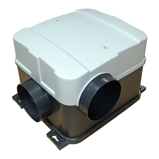
Unit Identification All maintenance/fault finding/repairs must be completed by a competent person. Safe isolation procedures must be followed when working on these units. Product Features Model CME3 Q + Part Number TP332A TP332HA Setback Speed (Set Automatically) ● Setback Speed ●... -
Page 4: Boost Overrun Timer
Boost Overrun Timer Boost Overrun Timer maintains the Boost Speed for a specific time variable between 0 and 30 minutes. The Boost Overrun Timer time is configured using step-less independent potentiometer. Integrated Humidity Sensor There are two variations, the function slightly varies depending upon the software on the control PCB. If the firmware on the PCB is FW0020-0100, then This continuously monitors the relative humidity (RH) of the extracted air and triggers Boost Speed when the relative humidity rises over the set threshold. -
Page 5: Pcb Configuration/Setting
PCB Configuration/Setting TP332A TP332HA PAGE 5 OF 10 FAULT FINDING FOR CME3Q+ ISSUE 1 03/04/20 894 The Crescent, Colchester Business Park, Colchester, Essex, CO4 9YQ United Kingdom Tel: +44 (0)1206 713800... -
Page 6: Dismantling
Dismantling Cover removal Remove the lid by unscrewing the two screws Caution This will then expose the control PCB and mains terminal. Mains terminal Above Remove the mains cable and the boost cable(s). Safety lockout procedure must be followed prior to disconnecting the mains from the unit. -
Page 7: Fault Finding
Fault Finding Unit Not Running 1. How are you determining the fan is not running? The fan may be running but is so quiet it is not audible. o Check flow rates at ceiling terminals o Increase fan speed, to see if it then becomes audible. 2. -
Page 8: The Unit Is Running At A Speed That Is Not Continuous, Boost Or Setback
The unit is running at a speed that is not Continuous, Boost Or SetBack Is the firmware on the PCB is FW0020-0200, if yes it is probable that the speed is ramping up/down due to humidity. Excessive Unit/System Noise 1. Is the unit providing the correct airflow, as calculated in Approved Document Part F? If set to high it may be possible to slow down the fan, thus reducing noise. -
Page 9: Both Continuous And Boost Speeds Have Changed
Both Continuous and Boost Speeds Have Changed HA Model The unit has re-set itself to factory setting, continuous is at %50 and boost is at 100%. This has probably occurred after a power surge or a power outage. Try Re-commissioning. A Models ... -
Page 10: Fig 3 Testing Pcb Inputs
Fig 3 Testing PCB Inputs Measure resistance across the terminals, this is easier across the soldered joints rather than the terminals block. If reading is open circuit, it is probable that 230v has been applied. If reading is approx. 15kΩ, then the circuit is ok. This only checks the switch input circuits and does not prove overall functioning i.e.
Need help?
Do you have a question about the CME3Q+ and is the answer not in the manual?
Questions and answers