
Related Manuals for Titon TP302A


Summary of Contents for Titon TP302A
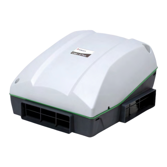
- Page 1 CME2 Q Plus CME2 Q Plus with Humidity Sensor TP302A TP302HA TP303A TP303HA CME2.1 Q Plus CME2.1 Q Plus with Humidity Sensor TP312A TP312HA TP313A TP313HA Extract Ventilation Unit Product Manual ventilation systems...
-
Page 2: Important Information
Warnings, Safety information and Guidance Important Information Important: read these instructions fully before the installation of this appliance 1. Installation of the appliance and accessories must be carried out by a qualified and suitable competent person and be car- ried out in clean, dry conditions where dust and humidity are at minimal levels. - Page 3 10. The appliance is not suitable for installation to the exterior of the dwelling. 11. This appliance can be used by children aged from 8 years and above and persons with reduced physical, sensory or mental capabilities or lack of experience and knowledge if they have been given supervision or instruction concerning use of the appliance in a safe way and understand the hazards involved.
-
Page 4: Table Of Contents
Important Information � � � � � � � � � � � � � � � � � � � � � � � � 2 TP302A, TP303A, TP312A & TP313A � � � � � � � � � � � �19 Control Parameters �... -
Page 5: Product Overview
Product Overview Dimensions This diagram details the overall size of the unit and the additional space required around the unit to allow for commissioning and future servicing and maintenance. Service Void All dimensions in mm... -
Page 6: Component Identification
Component Identification Cover / Scroll / Inlet Ring assembly Base Cover Scroll Inlet ring Unit components... -
Page 7: Packaging Contents
Packaging Contents Inspect the unit when taking delivery. Check the unit for damage and that all accessories have been supplied. The box contains: CME2 Q Plus or CME2.1 Unit x 1. ƒ Port covers x 3. ƒ This Product manual x 1. ƒ... -
Page 8: Product Features
The CME Q Plus is controllable by various volt-free switches and sensors. Mains switching can be achieved by use of the Titon Boxed Relay 5A TP 505. The following describes the controls and features of the CME Q Plus and how they are controlled. -
Page 9: Auto Setback Speed
Auto Setback Speed Setback Speed is a reduced ventilation rate. Auto Setback Speed is automatically set at the mid point between minimum possible Continuous Speed and the selected Continuous Speed. The Auto Setback Speed can be enabled by connection of a volt-free one-way switch, or combined with the Boost Speed with the 3 position switch TP 508. -
Page 10: Integrated Humidity Sensor
Integrated Humidity Sensor The units are fitted with an Integrated Humidity Sensor. This continuously monitors the relative humidity (RH) of the extracted air. The fan speed increases proportionally between Continuous Speed & Boost Speed depending on the measured %RH; see below for details. Boost Speed Continuous... -
Page 11: Installation
Installation Fixing The unit must be securely fixed to a smooth flat surface, any orientation is possible. Mark the four fixing hole centres using the Base as a template. Drill holes for fixings, use 4mm Pan Head screws. Always use a fixing type and length suited to the substrate type. - Page 12 Unscrew the 2 retaining screws that hold on the Cover and remove, retain the screws. Fit two screws from the Screw Pack through the preformed holes at the front of the Inlet Ring to securely fix the Inlet Ring/Scroll assembly to the Base.
-
Page 13: Ducting Connections
Ducting Connections Titon recommend the use of guidance given in the Domestic Ventilation Compliance Guide 2010 Edition ISBN-978 1 85946 378 9 and Approved Document Part F 2010 ISBN-978 1 85946 370 3 for all installations in the United Kingdom. - Page 14 10. All insulation to be the equivalent of at least 25mm of insulating material with a thermal conductivity of 0.04 W/(mK). 11. Ducting must be installed in such a way that resistance to airflow is minimised. 12. Ducting connected to the Extract Port to Outside must be to the external air outside the building envelope.
-
Page 15: How To Convert Port Cover
How to Convert Port Cover To enable fitment of 110 x 54mm ducting, modify the Convertible Port Cover by tearing out the ‘rip strip’ . When using the convertible port cover ensure the tear out section is completely removed. -
Page 16: Wiring Connections Access
Wiring Connections Access Access to the connections for mains, boost and other volt-free control functions is via removal of the Cover. Cables must be routed as shown and secured with clamps provided. Cable Access Internal Cable Routing... -
Page 17: Wiring Diagrams
Wiring Diagrams Double Pole Isolator 3A Fuse Supply Wiring Diagram 230V~50/60Hz EE 141 Volt-free boost switching of unit’s controller PCB using single-pole switches TP 502, TP 503, TP 507 1 2 3 and/or TP500 / TP501 Humidistat. TP500 / TP501 There maximum of 10 single pole switches or humidistats that can used. -
Page 18: Wiring Diagrams
Wiring Diagrams Volt-free setback switch or Volt-free setback switching of the unit’s normally open relay contacts controller PCB using single-pole latching switch and / or volt-free normally open relay contacts. To avoid the unit being inadvertently left in Setback Mode, it is recom- mended that only one latching switch is tted. -
Page 19: Tp302A, Tp303A, Tp312A & Tp313A
Commissioning TP302A, TP303A, TP312A & TP313A The fan speeds of the Titon CME2 & 2.1 Q Plus will require adjustment to ensure that the flow rates achieved provide adequate ventilation. The Titon CME2 & 2.1 Q Plus have 3 standard fan speed settings, Continuous Speed, Boost Speed and Setback Speed. -
Page 20: Commissioning
meters Boost Overrun Program Timer Switch xtract Continuous Boost Commissioning Remove Program / Run Header Link Boost Overrun Timer and place in the Program Position, fitted over both pins. The CME2 & 2.1 Q Plus will automatically switch Extract between Continuous Speed and Boost Speed when adjusting the Cont Boost... -
Page 21: Boost Overrun
Boost Overrun Boost Overrun Timer is variable between 0 and 30 minutes. Rotate potentiometer to change overrun time. Boost Overrun Timer adjustment can be done at any time without the need to move the Program / Run Header Link. Boost Overrun Pot positions Controller Reset Following a controller reset the ventilation system will need to be fully re- commissioned. -
Page 22: Tp302Ha, Tp303Ha, Tp312Ha & Tp313Ha
TP302HA, TP303HA, TP312HA & TP313HA The fan speeds of the Titon CME2 & 2.1 Q Plus will require adjustment to ensure that the flow rates achieved provide adequate ventilation. The Titon CME2 & 2.1 Q Plus has 3 standard fan speed settings, Continuous Speed, Boost Speed and Setback Speed. -
Page 23: Commissioning
Commissioning Remove Program / Run Header Link and place in the Program Position, fitted over both pins. The CME2 & 2.1 Q Plus will automatically switch between Setback Speed, Program / Run Continuous Speed and Boost Speed when adjusting the respective Header Link potentiometer. -
Page 24: Boost Overrun
Program / Run Header Link Boost Overrun Boost Overrun is variable between 0 and 30 minutes. Rotate potentiometer to change overrun time. Boost Overrun adjustment can be done at any time without the need to move the Program / Run Header Link. Boost Overrun Pot positions Humidity Sensor The Humidity Sensor’s set point is... -
Page 25: Controller Reset
Controller Reset Following a controller reset the ventilation system will need to be fully re- commissioned. The unit will need to be powered up during the reset procedure. Place the Program / Run Header Link in the Run Position Rotate the Setback, Continuous and Boost Speed adjustment potentiometers fully clockwise. -
Page 26: Maintenance
The CME2 Q Plus must be periodically cleaned internally. The maximum time between cleaning will depend on the local environment. Titon recommend the unit be cleaned every 3 – 4 years at a minimum. -
Page 27: Access To The Interior For Cleaning
Access to the Interior for Cleaning To gain access to the interior of the unit for cleaning – Unscrew the 3 retaining screws that hold on the Cover and remove Remove the 4 Scroll retaining screws. Using a flat bladed screw driver, un-clip Scroll from Inlet Ring by disengaging the 3 retaining clips. - Page 28 Remove the 3 retaining screws Using a flat bladed screwdriver, un-clip the Inlet Ring from Base by disengaging the 4 retaining clips. Carefully remove dust from the unit and fan blades using a vacuum cleaner. Wipe with damp cloth and mild detergent.
-
Page 29: Service Record
Service Record Serviced by Company Name Date Notes... -
Page 30: Technical
Static efficiency of fan in accordance with (EU) No 327/2011 35% - < 125W motor Declared maximum internal leakage rate (%) Energy performance of the filters Casing sound power level (L 57dB(A) Filter Warning (RVU) Internet address (for dissassembly instructions) www.titon.co.uk... - Page 31 Static efficiency of fan in accordance with (EU) No 327/2011 32% - < 125W motor Declared maximum internal leakage rate (%) Energy performance of the filters Casing sound power level (L 54dB(A) Filter Warning (RVU) Internet address (for dissassembly instructions) www.titon.co.uk...
- Page 32 Home Information Pack and used as a Service Record. MARKE TING DIVISION 894 The Crescent, Colchester Business Park, Colchester CO4 9YQ Tel: +44 (0) 1206 713800 Fax: +44 (0) 1206 543126 Email: ventsales@titon.co.uk Web: www.titon.com ©2022 TITON DO 5815 Issue 01...
Need help?
Do you have a question about the TP302A and is the answer not in the manual?
Questions and answers