Table of Contents
Advertisement
Quick Links
Advertisement
Table of Contents

Related Manuals for Titon CME3Q+


Summary of Contents for Titon CME3Q+
- Page 1 Fault Finding CME3Q+ Units With Switch Live Capability This document covers part number TP334HA PAGE 1 OF 9 FAULT FINDING FOR CME3Q+ LIVE ISSUE 1 03/04/20 894 The Crescent, Colchester Business Park, Colchester, Essex, CO4 9YQ United Kingdom Tel: +44 (0)1206 713800...
-
Page 2: Table Of Contents
Contents Unit Identification ................................. 3 Product Features ................................3 Setback Speed ............................... 3 Continuous Speed ..............................3 Boost Speed with Overrun Timer ......................... 3 Boost Overrun Timer ............................3 Integrated Humidity Sensor..........................3 Wiring Diagrams ................................4 PCB Configuration/Setting ............................5 Unit Dismantling ................................ -
Page 3: Unit Identification
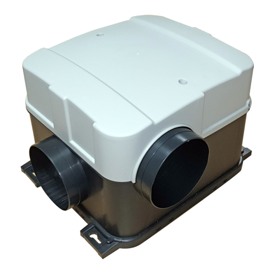
Unit Identification All maintenance/fault finding/repairs must be completed by a competent person. Safe isolation procedures must be followed when working on these units. Product Features Model CME2 Q Plus Part Number TP334HA Setback Speed ● Continuous Speed ● Boost Speed ●... -
Page 4: Wiring Diagrams
This continuously monitors the relative humidity (RH) of the extracted air and triggers Boost Speed when the relative humidity rises over the set threshold. The Humidity Sensor’s trigger point is variable from 55%RH to 85%RH and is configured using step-less independent potentiometer. If the firmware on the PCB is FW0020-0200, then This continuously monitors the relative humidity (RH) of the extracted air. -
Page 5: Pcb Configuration/Setting
PCB Configuration/Setting Unit Dismantling All maintenance/fault finding/repairs must be completed by a competent person Cover removal Remove the lid by unscrewing the two screws Caution This will then expose the control PCB and mains terminal. PAGE 5 OF 9 FAULT FINDING FOR CME3Q+ LIVE ISSUE 1 03/04/20 894 The Crescent, Colchester Business Park, Colchester, Essex, CO4 9YQ United Kingdom Tel: +44 (0)1206 713800... -
Page 6: Fault Finding
Mains terminal Above Remove the mains cable and the boost cable(s). Safety lockout procedure must be followed prior to disconnecting the mains from the unit. Mains cable clamping Removal of the Top Scroll. The scroll top is retained with six clips, some units may also use the four screw fixing points. -
Page 7: Unit Slows Down When Boosted
o Change units speed to determine if difference is then audible. Unit speeds can be determined by looking at the top of the relevant potentiometer and seeing where the arrows point. If the arrows on the continuous and boost pots are in the same or similar positions the flow rates and noise will be similar. -
Page 8: Condensation/Mould Within House
Condensation/Mould Within House 1. Is the unit being switched off, it must run 24/7 2. Where fitted, are trickle vents being left open? 3. Is the Boost function available and being used? N.B. not required in all properties depending upon calculations. -
Page 9: Fig 3 Molex Connector
Fig 3 Molex Connector Potentiometer Connections Fan Connector PCB Connector A - 10V, B - 0V, C - PWM & D - Tacho If this is not possible, try bridging the A and C terminals on the fan connector, the fan should then run at full speed.
Need help?
Do you have a question about the CME3Q+ and is the answer not in the manual?
Questions and answers