
Subscribe to Our Youtube Channel
Related Manuals for Titon CME1 Q Plus


Summary of Contents for Titon CME1 Q Plus
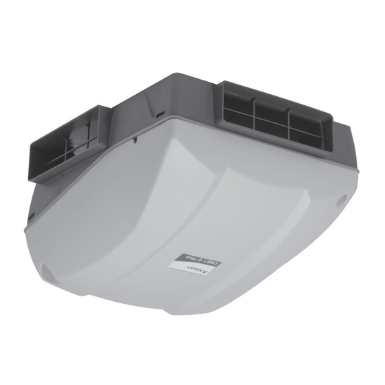
- Page 1 Titon CME1 Q Plus Mechanical Extract Ventilation Unit Product Manual ventilation systems CME1_Q_Plus_Product_Manual.indd 1 CME1_Q_Plus_Product_Manual.indd 1 24/09/2009 15:15:13 24/09/2009 15:15:13...
- Page 2 PCT Patent Application No PCT/GB2009/000114 CME1_Q_Plus_Product_Manual.indd 2 CME1_Q_Plus_Product_Manual.indd 2 24/09/2009 15:15:19 24/09/2009 15:15:19...
-
Page 3: Table Of Contents
Contents This is the Product Manual for the Titon CME1 Q Plus Introduction ........4 Ventilation is Vital . -
Page 4: Introduction
The Titon CME1 has been developed to meet these de- mands by extracting stale polluted air from the building whilst fresh air is provided by passive means. -
Page 5: Ventilation Is Vital
Ventilation is Vital onstruction methods used in older homes resulted in uncontrolled ventila- tion via air leaking through the building structure, such as small gaps around windows and doors or between walls and fl oors. These leaks allowed a large amount of air to move through a home largely unnoticed by the occupants. -
Page 6: How The System Works
How the System Works he Titon CME1 works by continually extracting stale polluted air from rooms where most moisture is generated. Fresh air is provided passively from outside to habital rooms, creating a fl ow of fresh, clean air throughout the home. The air travels from terminals built into the ceiling which are connected by hidden ducts to the unit. -
Page 7: How To Use The System
How to Use the System he unit runs automatically and should not be switched off , except for mainte- nance. If a boost switch has been installed, it can be used to increase the extract ventilation rate at times when moisture or pollutant levels are considered exces- sive. -
Page 8: Installation
Installation Safety and Guidance • The electrical installation of the appliance MUST be carried out by a suitably quali- fi ed competent person and all wiring must be in accordance with current I.E.E. Regulations and all appropriate standards and applicable regulatory guidance. •... -
Page 9: Transportation, Packaging & Storage
Installation Transportation, Packaging & Storage • Great care should be taken when transporting the appliance, DO NOT drop as damage may occur. • The unit must always be stored in a clean and dry environment. • Remove all packaging before installation but leaving duct port covers/bungs in place (if fi tted) until connecting ducting. -
Page 10: Dimensions
Installation Dimensions This diagram shows the overall dimensions of the unit, and the additional space required around the unit once installed to allow for future servicing and maintenance. Service Void All dimensions in mm CME1_Q_Plus_Product_Manual.indd 10 CME1_Q_Plus_Product_Manual.indd 10 24/09/2009 15:15:21 24/09/2009 15:15:21... -
Page 11: Component Identifi Cation
Installation Component Identifi cation Cover / Scroll / Inlet Ring assembly Base Cover Scroll Inlet ring Base CME1 Unit components CME1_Q_Plus_Product_Manual.indd 11 CME1_Q_Plus_Product_Manual.indd 11 24/09/2009 15:15:22 24/09/2009 15:15:22... -
Page 12: Fixing
Installation Fixing The CME1 must be securely fi xed to a smooth fl at surface, any orientation is possible. Mark the four fi xing hole centres using the BASE as a template Drill holes for fi xings, use 4mm Pan Head screws. Always use a fi xing type and length suited to the substrate type. - Page 13 Installation Fixing Unscrew the 2 retaining screws that hold on the COVER and remove, retain the screws. Fit two screws through the pre- formed holes at the front of the INLET RING. to securely fi x the INLET RING/SCROLL assembly to the BASE. Fit one screw through the preformed hole in the back of the BASE.
-
Page 14: Ducting Best Practice
Installation Ducting Best Practice • The use of fl exible ducting must be kept to a minimum and it should always be pulled taut. • If applicable, Fire Dampers must be fi tted to duct work at appropriate locations in accordance with Building Regulations. -
Page 15: Ducting Connection
Installation Ducting Connection • 204mm x 60mm ducting fi ts inside the ports. • 110mm x 54mm ducting fi ts inside the convertible port cover • All joints must be adequately sealed using a suitable ducting tape or silicone type sealant. CME1_Q_Plus_Product_Manual.indd 15 CME1_Q_Plus_Product_Manual.indd 15 24/09/2009 15:15:28... - Page 16 Installation Ducting Connection • To enable fi tment of 110x54mm ducting, modify the convertible port cover by tearing out the ‘rip strip’ . • When using the convertible port cover ensure the tear out section is completely removed. • Unused extract ports must be fi tted with non-converted or undamaged port covers.
- Page 17 Installation Notes CME1_Q_Plus_Product_Manual.indd 17 CME1_Q_Plus_Product_Manual.indd 17 24/09/2009 15:15:30 24/09/2009 15:15:30...
-
Page 18: Wiring
Installation Wiring WARNING: The unit MUST be earthed. All wiring must conform to current I.E.E. Wiring Regulations and all applicable standards and Building Regulations. • The unit is suitable for 230V~50Hz Single phase supply fused at 3A. • A double pole isolation switch with contact separation of at least 3mm must be used to connect the appliance to the fi xed wiring. - Page 19 Installation Wiring Cable Access Internal Cable Routing Boost Control Wiring Diagram, Low Voltage Only CME1_Q_Plus_Product_Manual.indd 19 CME1_Q_Plus_Product_Manual.indd 19 24/09/2009 15:15:30 24/09/2009 15:15:30...
-
Page 20: Quick Commission
Quick Commissioning he speed of the Titon HRV1 Q Plus will require adjustment to ensure the fl ow rates achieved provide adequate ventilation in accordance with all relevant Building Regulations and applicable Standards. The Titon HRV1 Q Plus has two commissioning modes •... - Page 21 Quick Commissioning Speed 1 Speed 2 Speed 3 Speed 4 on dip on dip on dip on dip 1 2 3 4 1 2 3 4 1 2 3 4 1 2 3 4 12.5% 37.5% Speed 5 Speed 6 Speed 7 Speed 8 on dip...
-
Page 22: Full Commission Mode
Full Commission Mode To fully commission the unit for optimum effi ciency, each step below MUST be followed in sequence: Power up the Titon CME1 Q Plus. Gain access to the control board located under the COVER. Continuous speed setting Move the jumper from the STORED position to the ON position. - Page 23 Full Commissioning Continuous Mode on dip 1 2 3 4 Continuous Mode switch setting in Full Commission Mode Speed 1 Speed 2 Speed 3 Speed 4 on dip on dip on dip on dip 1 2 3 4 1 2 3 4 1 2 3 4 1 2 3 4 12.5%...
-
Page 24: Boost Speed Setting
Full Commissioning Boost Speed Setting Select Boost mode on switch 1 ON. Boost Mode Select required range for boost on dip speed using switches 2 to 4 on the speed selection switch. 1 2 3 4 Fine adjustment within each speed range can be carried out using the potentiometer (POT) on the control Boost Mode switch setting in Full... -
Page 25: Resetting The Controller
Full Commissioning Boost Speed Settings Once the Continuous and Boost speeds have been set, remove the jumper and return to the stored position. Select required boost overrun using Stored switch 1 and 2 on the speed selec- tion switch. Check boost activation by triggering Jumper Positions the remote boost switch device. -
Page 26: Maintenance
Maintenance Cleaning The CME1 must be periodically cleaned internally. The maximum time between cleaning will depend on the local environment, however every 3 – 4 years is recom- mended. WARNING: The unit uses a 230V ~ supply and contains rotating mechanical parts. Isolate the unit from mains power supply and allow suffi cient time for all moving parts to stop before undergoing any Servicing or Maintenance. - Page 27 Maintenance Cleaning • Using a fl at bladed screw driver, un-clip SCROLL from INLET RING by disengaging the 3 retaining clips. Ensure that the SCROLL is supported and does not strain the cables. • Remove the 3 retaining screws. CME1_Q_Plus_Product_Manual.indd 27 CME1_Q_Plus_Product_Manual.indd 27 24/09/2009 15:15:35 24/09/2009 15:15:35...
- Page 28 Maintenance Cleaning • Using a fl at bladed screwdriver, un- clip the INLET RING from BASE. by disengaging the 4 retaining clips. • Carefully remove dust from the unit and fan blades using a vacuum cleaner. • Wipe with damp cloth and mild detergent. •...
-
Page 29: Declaration Of Conformity
We declare that the equipment detailed below conforms to the requirements of EC council directives relating to electro- magnetic compatibility and safety of electrical equipment. Equipment type: Titon CME1 Q Plus Description of equipment: Mechanical ventilation unit Relevant EC Council Directives:... - Page 30 Service Record Serviced by Company name Date Notes CME1_Q_Plus_Product_Manual.indd 30 CME1_Q_Plus_Product_Manual.indd 30 24/09/2009 15:15:39 24/09/2009 15:15:39...
-
Page 31: Service Record
Service Record Serviced by Company name Date Notes CME1_Q_Plus_Product_Manual.indd 31 CME1_Q_Plus_Product_Manual.indd 31 24/09/2009 15:15:39 24/09/2009 15:15:39... - Page 32 Home Information Pack and used as a service record. MARKETING DIVISION International House, Peartree Road, Stanway, Colchester, Essex CO3 0JL Tel: +44 (0) 1206 713800 Fax: +44 (0) 1206 543126 Email: ventsystems@titon.co.uk Web: www.titon.com BM 834 iss03 CME1_Q_Plus_Product_Manual.indd 32 CME1_Q_Plus_Product_Manual.indd 32...
Need help?
Do you have a question about the CME1 Q Plus and is the answer not in the manual?
Questions and answers