Advertisement
Quick Links
TEMPERATURE AND HUMIDITY
DIGITAL CONTROLLER
Ver.02
1. DESCRIPTION
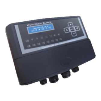
Humitech Super
is an environment controller with 15 control outputs built-in. It monitors environment temperature and humidity in order to
control a wide range of equipment, such as: Water Sprayer, Cooling, Heating and Ventilation systems.
2. APPLICATION
It is designed to be used together with Evaporation Cooling Systems for thermal comfort in gymnasiums, exposition pavilions, supermarkets,
machine rooms, cattle breeding installations, incubators, poultry housing and swine housing.
3. TECHNICAL SPECIFICATIONS
- Power Source:
90 ~ 264 Vac ± 10% (50/60Hz)
- Controlled Temperature:
-50 to 105 °C / -58 to 221 °F (resolution: 0.1°C / 1°F)
- Controlled Humidity:
0 to 100% RU (resolution: 0.1% RH)
- Commands: Alarms:
Two NC relay contacts (max. 3A)
- Control Outputs:
13 NO relay contacts (max. 300mA)
- Dimensions (W x H x D):
220x134x54mm
- Operation Temperature:
0 to 40°C
- Operation Humidity:
10 to 90% RH (without condensation)
4. OUTPUT DESCRIPTION
Fan Group 1
Fan Group 2
Fan Group 3
Fan Group 4
Fan Group 5
Fan Group 6
Fan Group 7
Fan Group 8
M
M
Minimum Ventilation
I
I
N
N
Cooling
Water Sprayer 1
Water Sprayer 2
Heating
Alarm 1
Alarm 2
5. SERVICE SETTINGS (ADVANCED SETTINGS)
Humitech Super
operation settings (among others) can be configured for device outputs in the advanced settings menu. To enter the
advanced settings menu hold
and
pressed for 2 seconds until the Access Code selection is displayed. To enter the selection press
return to the previous menu level press
. The parameter value can be changed by pressing
operation or the
key to cancel it. The available menu selections are:
01-Code
Access Code
02-Min. Ventilat
Minimum Ventilation parameters
03-Vent. Groups
Fan Group parameters
04-Heating
Heating parameters
05-Cooling
Cooling parameters
06-Fogger
Water Sprayer parameters
07-Alarms
Alarm parameters
Press
to enter the selected function. The current value starts to blink when the parameter setting is configurable.
The function value can be changed by using
and
keys. Press
Function
Offset 1
Temp
description
C01@ 10.0 #
Function code
Function value
Function units
or
. Press the
key to confirm the
08-Datalogger
Datalogger parameters
09-Program
Daily Setpoint configuration
10-Config
General Configuration parameters
11-Clock Adjust
Date & Time settings
12-Name Adjust
Controller Name
13-Clear Log
Clear Datalogger Memory
again to set the new value or press
to cancel it and return.
01
5.1 Access Code
You must key in 123 to enter this selection and have the advanced parameter settings enabled for configuration.
5.2 Minimum Ventilation
Parameters related to the Minimum Ventilation output (
®
Fun
V01
Minimum Ventilation OFF Relative Temperature
V02
Minimum Ventilation ON Relative Temperature
V03
Time unit of minimum ventilation when activated.
V04
Time unit of minimum ventilation when deactivated
V05
Minimum Ventilation output ON Time.
V06
Minimum Ventilation output OFF Time.
(*) Depends on the value set in V03
(**) Depends on the value set in V04
V01-Minimum Ventilation OFF Relative Temperature
Temperature difference from the Main Setpoint. When the average temperature is below this value the Minimum Ventilation output is always OFF.
V02-Minimum Ventilation ON Relative Temperature
Temperature difference from the Main Setpoint. When the average temperature is above this value the Minimum Ventilation output is always ON.
V03-Time unit of minimum ventilation when activated.
Function V05 time unit settings.
V04-Time unit of minimum ventilation when deactivated
Function V06 time unit settings.
V05-Minimum Ventilation output ON Time
Time that the Minimum Ventilation output is ON when it is in a cyclic operation. If set to '0' the output will permanently be ON. The time unit of this
parameter is set on V03.
V06-Minimum Ventilation output OFF Time
Time that the Minimum Ventilation output is OFF when it is in a cyclic operation. The time unit of this parameter is set on V04.
5.3 Fan Groups
Parameters related to the Fan Groups (
Fun
G01
Fan Group Relative Temperature 1
Fan Group Hysteresis 1
G02
, to
G03
Fan Group Relative Temperature 2
Fan Group Hysteresis 2
G04
G05
Fan Group Relative Temperature 3
Fan Group Hysteresis 3
G06
G07
Fan Group Relative Temperature 4
Fan Group Hysteresis 4
G08
G09
Fan Group Relative Temperature 5
Fan Group Hysteresis 5
G10
G11
Fan Group Relative Temperature 6
G12
Fan Group Hysteresis 6
G13
Fan Group Relative Temperature 7
G14
Fan Group Hysteresis 7
G15
Fan Group Relative Temperature 8
G16
Fan Group Hysteresis 8
Fan Group Relative Temperature
Temperature difference from the Main Setpoint. When the average temperature is above this value the corresponding Fan Group will be ON.
Fan Group Hysteresis
Temperature difference from the Fan Group Relative Temperature for turning the corresponding fan group OFF.
M
M
I
I
M
M
) operation:
N
N
I
I
N
N
CELSIUS
FAHRENHEIT
Description
Min.
Max.
Unit
Standar Min.
Max.
-50.0
50.0
°C
0.0
-90
90
-50.0
50.0
°C
5.0
-90
90
0-sec.
2-hou.
-
0-sec.
0-sec.
2-hou.
0-sec.
2-hou.
-
1-min.
0-sec.
2-hou.
0
999
(*)
30
0
999
0
999
(**)
3
0
999
......
) output operation:
CELSIUS
FAHRENHEIT
Description
Min. Max.
Standar Min. Max.
Unid.
-50.0
50.0
°C
5.0
-90
90
°C
1.0
15.0
1.0
1
27
-50.0
50.0
°C
10.0
-90
90
1.0
15.0
°C
1.0
1
27
-50.0
50.0
°C
15.0
-90
90
1.0
15.0
°C
1.0
1
27
°C
-50.0
50.0
20.0
-90
90
1.0
15.0
°C
1.0
1
27
°C
-50.0
50.0
25.0
-90
90
1.0
15.0
°C
1.0
1
27
°C
-50.0
50.0
30.0
-90
90
1.0
15.0
°C
1.0
1
27
°C
-50.0
50.0
35.0
-90
90
1.0
15.0
°C
1.0
1
27
°C
-50.0
50.0
40.0
-90
90
1.0
15.0
°C
1.0
1
27
02
Unit
Standar
°F
0
°F
9
-
0-sec.
-
1-min.
(*)
30
(**)
3
Standar
Unid.
°F
9
°F
2
°F
18
°F
2
°F
27
°F
2
°F
36
°F
2
°F
45
°F
2
°F
54
°F
2
°F
63
°F
2
°F
72
°F
2
Advertisement

Related Manuals for Full Gauge Controls HUMSUPV2-01T-11953


Summary of Contents for Full Gauge Controls HUMSUPV2-01T-11953
- Page 1 5.1 Access Code You must key in 123 to enter this selection and have the advanced parameter settings enabled for configuration. TEMPERATURE AND HUMIDITY DIGITAL CONTROLLER 5.2 Minimum Ventilation Parameters related to the Minimum Ventilation output ( ) operation: Ver.02 ®...
- Page 2 5.4 Heating N01-Water Sprayer 1 Relative Temperature Temperature difference from the Main Setpoint. When the average temperature is above this value, the Water Sprayer output 1 will be ON. Parameters related to the Heating output ( ) operation: N02-Water Sprayer 1 Hysteresis CELSIUS FAHRENHEIT Temperature difference from the Water Sprayer 1 Relative Temperature for turning the Water Sprayer 1 OFF.
- Page 3 5.8 Datalogger Main Setpoint for the program 11 -50.0 105.0 50.0 °C °F Parameters related to the operation of controller internal memory. Program 12 duration Days Days CELSIUS FAHRENHEIT 45.0 Main Setpoint for the program 12 -50.0 105.0 °C °F Description Min.
-
Page 4: Operation
C07-Temperature Units 8. PROGRAMMING MODE FUNCTIONS Temperature measurement units The Programming mode function menu allows you to easily access the operation selections when the controller uses the Daily Setpoint Programs. To enter this menu, press the key repeatedly. MENU C08-RS485 Network Address This menu is available only when the controller is working in the Programming Mode selectable as per section Operation Modes”. - Page 5 surpasses 50.0°C (30.0°C + 20.0°C), Water Sprayer 2 output is turned ON. When the relative air humidity is below 20.0% RH Water Sprayer 1 9.4 Heating output is turned ON. If humidity falls below 8.0%RH, Water Sprayer 2 output is turned ON. The Heating output operates based on the Main Setpoint and works as follows: When the average temperature is below 45.0°C ( 30.0°C + 20.0°C - 5.0°C...
- Page 6 Operation mode (OFF mode) Main screen (OFF mode) The time between samples can be configured in the parameter Time Between Samples . If you want to force the controller to sample Average Current operation temperature/humidity when data changes, you can configure this in the parameter Average temperature variation to force data recording and Humidity temperature...
- Page 7 12. INSTRUMENT FIXATION MODE 13. WIRING DIAGRAM 12.1 DIN mount fixation TEMPERATURE/ HUMIDITY SENSOR WIRING PANEL ORANGE GREEN BROWN D I N YELLOW USB INPUT POWER AND CONTROL OUTPUTS Instrument Wall SERIAL COMMUNICATION RS-485 DIN rail TEMPERATURE SENSOR 2 (OPTIONAL) ALRM 1 ALRM 2 POWER SUPPLY...
- Page 8 HUMITECH SUPER Used to connect more than one instrument to the Device used to establish the Interface. The wire's connections must be made in connection Full Gauge Controls’ agreement with the following rules: terminal of the ® instruments with the Sitrad Offset S1 C01@ 10.0#...
Need help?
Do you have a question about the HUMSUPV2-01T-11953 and is the answer not in the manual?
Questions and answers