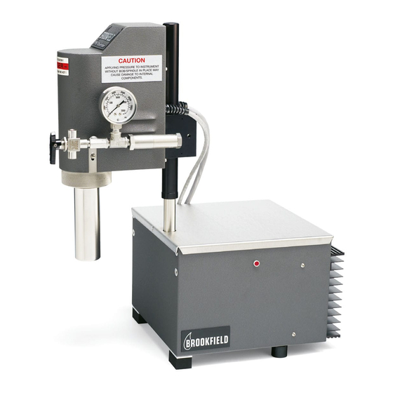
Sign In
Upload
Manuals
Brands
Brookfield Manuals
Measuring Instruments
PVS RHEOMETER
Brookfield PVS RHEOMETER Manuals
Manuals and User Guides for Brookfield PVS RHEOMETER. We have
1
Brookfield PVS RHEOMETER manual available for free PDF download: Operation Instructions Manual
Brookfield PVS RHEOMETER Operation Instructions Manual (68 pages)
Brand:
Brookfield
| Category:
Measuring Instruments
| Size: 3.93 MB
Table of Contents
Table of Contents
2
Section 1 - PVS Rheometer Description
8
Introduction
8
Features and Benefits
8
Standard Equipment
8
Figure 1-1: Typical Brookfield Model PVS Rheometer
9
Rheovision Software
10
Rheovision System Requirements
10
Registering Rheovision
10
Theory of Operation
10
Table 1-1: Rheovision System Requirements
10
Figure 1-2: PVS Rheometer and Optional Bath
11
Specifications
12
Required Utilities
12
Operating Environment
12
Table 1-2: Model PVS Rheometer Specifications
12
Table 1-3: Utility Requirements
12
Geometry Sets
13
Component Identification
13
Rheometer Head
13
Table 1-4: Geometry Sets
13
Sample Cup
14
Power Base
14
Sensing Stack
14
Stator/Bob
14
Torsion Element/Mounting Tube Assembly
14
Torsion Element Guard
14
Safety Relief Valve
14
Pressure Transducer
14
Personal Computer
15
Figure 1-3: Typical PVS Rheometer Component Identification
15
Options
16
Heating/Cooling Bath
16
Laptop Computer
16
Additional Geometry Sets
16
High Surface Area Triple Annulus
16
Contacting Brookfield Engineering Laboratories, Inc
16
Section 2 - Installation
17
Unpacking and Inspection
17
Tools Required for Installation
17
PVS Rheometer Installation (Without Triple Annulus)
18
Bath Installation
18
Power Base Installation
18
Figure 2-1: Rheometer Head Position and Sample Cup Height
19
Personal Computer Installation
20
Rheovision Software Installation
20
Figure 2-2: PVS Rheometer Rear Panel Cable Connections
20
Safety and Precaution Symbols
21
Section 3 - Operation
22
Power
22
Turning Power on
22
Turning Power off
22
Starting Rheovision
22
Baffle, Stator/Bob and Sample Cup Installation
23
Figure 3-1: Stator/Bob Mounting Tube Alignment (End View)
23
Figure 3-2: Orientation and Force Applied to Stator/Bob During Installation
24
Table 3-1: Stator/Bob Sample Volume
24
Figure 3-3: Sample Cup, Stator/Bob and Baffle Installation
25
PVS Rheometer Installation (with Triple Annulus)
26
Figure 3-4: Stator/Bob Mounting Tube Alignment (End View)
27
Figure 3-5: Triple Annulus Installation
28
Cleaning of Wetted Parts
29
Torque Sensor Calibration Test
30
Section 4 - Rheovision Software
31
What's New with Rheovision
31
Getting Started
32
Figure 4-2: Login Screen
32
Setting up Security
33
Figure 4-3: Security/Database
33
Figure 4-4: Permissions
33
Figure 4-5: Groups
34
Figure 4-6: User Membership
34
Main Navigation Panel
35
Main Tool Bar
36
Figure 4-7: Options Tab
36
Figure 4-8: Calibration Tab
36
Figure 4-9: Security/Database Tab
37
Dashboard
38
Figure 4-10: Lip Seal Tab
38
Figure 4-11: Dashboard
38
Favorites
39
Figure 4-12: Favorites
39
Tests/Programs
40
Test Header Parameters
40
Figure 4-13: Tests/Programs
40
Quick Test Wizard
41
Figure 4-14: Test Header Parameters
41
Figure 4-15: Quick Test Screen
41
Figure 4-16: Test Wizard Opening Screen
42
Figure 4-17: Enter Speed and Time
42
Figure 4-18: Enter MIX Step, Duration and Data Interval
43
Figure 4-19: Enter Temperture Setpoint
43
Figure 4-20: Choose Data Collection
44
Figure 4-21: Enter Ramps
44
Quick Test List Screen
45
Figure 4-22: Name Test Template
45
BEAVIS Programs
46
Figure 4-23: Less Detail Shown
46
Figure 4-24: BEAVIS Tests Screen
46
BEAVIS Commands
47
Table 4-1: BEAVIS Commands
47
BEAVIS Program Screen
48
Figure 4-25: BEAVIS Program Screen
48
Building Programs
49
Find Data
49
View Data Graphs
50
Appendix
50
Figure 4-26 Find Data
50
Communications
51
Figure 4-27: Communication Selection
51
Section 5 - Troubleshooting
52
Introduction
52
Table 5-1: PVS Rheometer Troubleshooting Procedures
52
Communication Problems
54
Instrumentation Setup
54
Figure 5-1: Communications Warning Pop-Up Window
54
Windows XP Sp3/Vista/W7
55
Section 6 - PVS Sensing Stack Replacement
56
Tools Required
56
Disassembly
56
Reassembly
58
Figure 6-1: PVS Rheometer Component Identification
61
Figure 6-2: PVS Sensing Stack (Exploded View)
62
Appendix - Customer Support
63
Appendix B - Drawings
64
Figure B-1: RS-232 Cable Drawing
64
Appendix C - Calculations
66
Table C-1: Geometry (Spindle) Factors
66
Advertisement
Advertisement
Related Products
Brookfield PFT Powder Flow Tester
Brookfield PFT3230
Brookfield PFT3115
Brookfield CAP 1000+
Brookfield CAP 2000+H
Brookfield CAP 2000+L
Brookfield CP-40
Brookfield CP-41
Brookfield CP-42
Brookfield CP-51
Brookfield Categories
Measuring Instruments
Temperature Controller
Laboratory Equipment
Door Opening System
More Brookfield Manuals
Login
Sign In
OR
Sign in with Facebook
Sign in with Google
Upload manual
Upload from disk
Upload from URL