
Related Manuals for Daiichi Electronics SMLC-110L


Summary of Contents for Daiichi Electronics SMLC-110L
- Page 1 SMLC-213-154 INSTRUCTION MANUAL MAXIMUM (MINIMUM) SUPER MULTI-METER SMLC-110L Hardware Model D...
- Page 2 Location corresponding to the usage environment and use conditions. Aluminum electrolytic capacitors are used for products. Please energize the power supply within one year after purchase. Countermeasures against troubles. If this product breaks down within the warranty period, it will be repaired by DAIICHI ELECTRONICS.
- Page 3 SMLC-213-154 Disposal Please dispose this product as industrial waste (non-combustible). Mercury parts and a nickel-cadmium battery are not used for this product. Warranty period. The warranty period of the product is one year after the date of delivery. ...
- Page 4 SMLC-213-154 Phase voltage input Line voltage input № Setting item Vo 190V Vo 110V Vo 190V Vo 110V Output factor 1 Maximum zero-phase voltage Maximum zero-phase voltage Output factor 2 V(RS) V(RS) Analog output Output factor 3 V(ST) V(ST) 1 Output factor 4 V(TR) V(TR)
-
Page 5: Table Of Contents
SMLC-213-154 Content 1. Product outline ・・・・・・・・・・・・・・・・・・・・・・・・・・・・・・・・・・・・・・・・・・・・・・・・・・・・・・・・・・・・・・ 5 1.1 Usage of product ・・・・・・・・・・・・・・・・・・・・・・・・・・・・・・・・・・・・・・・・・・・・・・・・・・・・・・・・・・ 5 1.2 Features of product ・・・・・・・・・・・・・・・・・・・・・・・・・・・・・・・・・・・・・・・・・・・・・・・・・・・・・・・ 5 2. The name and function of each part ・・・・・・・・・・・・・・・・・・・・・・・・・・・・・・・・・・・・・・・・・・・ 6 3. Preparation 3.1 Installation ・・・・・・・・・・・・・・・・・・・・・・・・・・・・・・・・・・・・・・・・・・・・・・・・・・・・・・・・・・・・・・ 7 3.2 Connections ・・・・・・・・・・・・・・・・・・・・・・・・・・・・・・・・・・・・・・・・・・・・・・・・・・・・・・・・・・・・・・・ 8 4. Operation ・・・・・・・・・・・・・・・・・・・・・・・・・・・・・・・・・・・・・・・・・・・・・・・・・・・・・・・・・・・・・・・・・・・・ 9 4.1 The screen change and function by switch operation ・・・・・・・・・・・・・・・・・・・・・・・・... -
Page 6: Product Outline
SMLC-213-154 1. Product outline 1.1 Usage of product This single unit can measure and monitor phase voltage ×3, line voltage ×3, zero-phase voltage, frequency. 3-phase voltage can select two types, a phase voltage input product and a line voltage input product, according to a usage. -
Page 7: The Name And Function Of Each Part
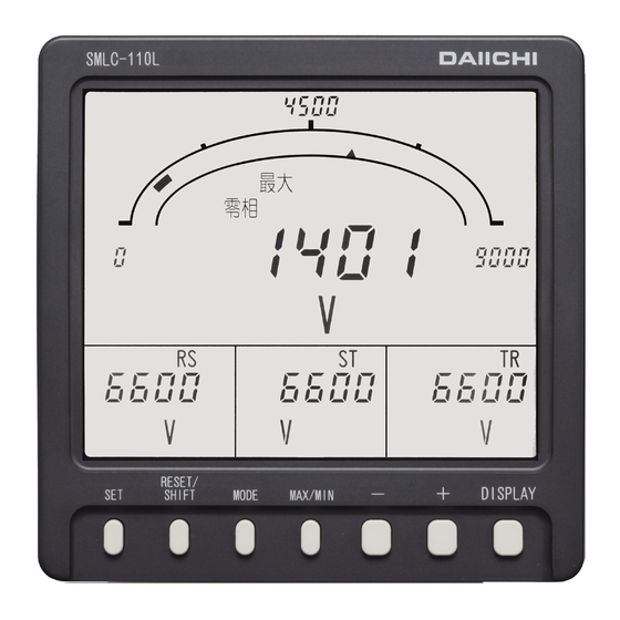
SMLC-213-154 2. The name and function of each part Digital display Measurement monitor can watch 4 elements at the same time. Bar graph display Sub-monitor (Left) Main monitor The measurement value of the main Sub-monitor (Center) Sub-monitor (Right) monitor is indicated by the analog. -
Page 8: Preparation
SMLC-213-154 3. Preparation 3.1 Installation Mount the unit by the attached M5 nuts to a panel of thinner than 10mm, referring to the following external dimensions drawing and panel cutout. Fasten these nuts with tightening torque 2.0 to 2.5N・m. ● Dimension diagram ●... -
Page 9: Connections
SMLC-213-154 3.2 Connections Please perform connection after referring to the following wiring diagram. 6 ■ Connection drawing ( ● 3-phase voltage (Phase voltage input), ● 3-phase voltage (Line voltage input ), 7 Zero-phase voltage Zero-phase voltage ( AUX.SUPPLY AUX.SUPPLY ANALOG OUTPUT 1 ANALOG OUTPUT 1 ANALOG OUTPUT 2 ANALOG OUTPUT 2... -
Page 10: Operation
SMLC-213-154 4. Operation The function of switch Switch Function If it continues pushing 3 seconds or more, it will change to setting mode. In setting mode, it is used for the determination of a set point. Various kinds of alarms are reset. The maximum value and the minimum value are reset in the RESET/SHIFT maximum minimum measurement display. -
Page 11: The Screen Change And Function By Switch Operation
SMLC-213-154 4.1 The screen change and function by switch operation This product changes various screens by switch operation. Here, the change step of the screen by switch operation is explained. Display mode + , - Main monitor Push 3 seconds display-element Setting mode 1 No operation,... -
Page 12: The Kind Of Display
SMLC-213-154 4.2 The kind of display 4.2.1 Measurement display A measurement value display has the two following types of displays. The change of the measurement display element of the main monitor by switch operation and the change of the phase / line display of voltage is possible (temporarily). In an instantaneous measurement display, if switch operation is not performed for 10 minutes after changing a display element, it returns to the original measurement display element automatically. - Page 13 SMLC-213-154 ② Ground fault phase detection display The maximum zero-phase voltage and the minimum phase voltage of each phase are displayed. (Display-element fixation) It is possible to distinguish the ground fault phase at the case of ground fault occurrence by displaying these measurement values.
-
Page 14: Alarm Detection Display
SMLC-213-154 4.2.2 Alarm detection display The alarm value setting is a possible measurement factor (zero-phase voltage and line voltage), it displays in case an input exceeds a set point. Besides the usual measurement display, the detected factor is displayed on a screen upper case. In addition, in case setting OFF (not use) as measurement factor, it does not detect. -
Page 15: Setting Display
SMLC-213-154 4.2.3 Setting display This is display for various setting. There are three types of setting modes according to the contents of setting. Refer to "5. Setting" for the operation in setting mode, and the detailed contents of a setting. Current setting ①... -
Page 16: Operation
SMLC-213-154 4.3 Operation 4.3.1 The main monitor display-element change The measurement display element of the main monitor is changed. A change is performed by + -. This operation can perform the maximum and the minimum display other than instantaneous measurement display. After changing a measurement display element, if a switch is not operated for 10 minutes, it will return to the original measurement display element automatically. -
Page 17: Ground Fault Phase Detection Display Change
SMLC-213-154 4.3.3 Ground fault phase detection display change A measurement display and a ground fault phase detection display are changed. A change is performed by MODE . This operation can perform the maximum and the minimum display other than instantaneous measurement display. In addition, even if it elapses for 10 minutes without operating a switch, it does not return to the original display. -
Page 18: Setting Mode
SMLC-213-154 4.3.5 Setting mode Various kinds of setting are performed. Setting mode is three types, and operations are different. DISPLAY is pushed in case it returns to the original measurement display. And, if a switch is not operated for 10 minute after a set point check, it will return to the original measurement display automatically. Operation and the contents of setting (detail) in setting mode, please refer to "5 Setting". -
Page 19: Reset
SMLC-213-154 4.3.6 Reset Various kinds of reset are performed. The kind of reset is as follows and operations are different, respectively. Reset of maximum value and minimum value (it updates to the instantaneous value at the time), Alarm output reset (OFF of an alarm output (at the case of manual reset setting)). And, the operation from each measurement display constitutes conditions at each reset. - Page 20 SMLC-213-154 (2) Alarm reset In case an alarm return method is set to “HOLD (manual return)”, an alarm output is reset (output OFF). (With an alarm output option) However, an output is not turned off by this operation, in case an alarm continues and it has caused. And, this operation is unnecessary in case setting as "AUTO (automatic return)”...
-
Page 21: Setting
SMLC-213-154 5. Setting 5.1 Function table This product has each function setting with a front switch. Setting mode 1. Function table Default Important Set No. Function Functional description Page setting setting Set the display combination pattern of the digital 4 Display pattern Pattern 1 ○... - Page 22 SMLC-213-154 Setting mode 2. Function table Default Important Set No. Function Functional description Page setting setting Voltage range Set the voltage measurement range (VT ratio). 6600V ○ Zero-phase voltage Display ON/OFF of ×1/√ is set as a scale of zero-phase ×1/√...
-
Page 23: Setting Table
SMLC-213-154 5.2 Setting table Setting item changes by the specification of a product, or the existence of an option. (1) Important setting Each parenthesized number shows a setting number and this number is displayed on the setting screen. Items Setting and operation procedures Page Press SET and RESET/SHIFT together for longer than 3 seconds Setting of... - Page 24 SMLC-213-154 Items Setting and operation procedures Page Press SET and RESET/SHIFT together for longer than 3 seconds Press MODE Setting of external (211) (221A) operation input 1 Press MODE Select an function by + and - Press SET function. (231) (231) Selected function is entered Press DISPLAY...
- Page 25 SMLC-213-154 (3) Setting of frequency measurement range Each parenthesized number shows a setting number and this number is displayed on the setting screen. Items Setting and operation procedures Page Press SET and RESET/SHIFT together for longer than 3 seconds Press RESET/SHIFT Setting of (211) measurement range...
- Page 26 SMLC-213-154 (7) Setting of zero-phase voltage detection. Each parenthesized number shows a setting number and this number is displayed on the setting screen. Items Setting and operation procedures Page Press SET for longer than 3 seconds Press MODE Press MODE Press MODE Setting of upper (111)
-
Page 27: Setting In Detail Explanation
SMLC-213-154 5.3 Setting in detail explanation 5.3.1 Setting mode 1 Setting mode 1 is selected by pressing 3 seconds SET switch for longer than 3 seconds. 111 to 116 DISPLAY Pushing MODE switch performs movement Display setting of setting item. MODE The present mode can be returned to the display mode by pressing DISPLAY... - Page 28 SMLC-213-154 Display combination setting RESET/SHIFT RESET RESET RESET RESET RESET Bar graph Combination Sub-monitor Sub-monitor Sub-monitor Main monitor /SHIF /SHIF /SHIF /SHIF /SHIF display (Left) (Center) (Right) factor Pattern 1 MVo:1 V(RS):4 V(TR):6 Main monitor V(ST):5 + - + -...
- Page 29 SMLC-213-154 (2) 121AL to 126AL Alarm output setting 【With an alarm output option】 Various setting and an output test are performed about an alarm output. And, it sets about the corresponding alarm output. 121AL 122AL 123AL RESET/ RESET/ Alarm 1 Alarm 1 factor Alarm 1 test SHIFT...
- Page 30 SMLC-213-154 (3) 131H to 133 3-phase voltage detection setting 3-phase voltage factor performs a setting of upper limit alarm value and lower limit alarm value. New setting 131H 132L RESET/ RESET/ Current setting Setting No. 3-phase voltage 3-phase voltage Line-voltage SHIFT SHIFT upper limit...
- Page 31 SMLC-213-154 (4) 141H to 143 Zero-phase voltage detection setting Setting of the alarm value of a zero-phase voltage factor, the response time, and a display change is performed. 141H New setting RESET/ Zero-phase Ground-fault phase RESET/ Current setting Setting No. SHIFT Response time voltage upper...
-
Page 32: Setting Mode 2
SMLC-213-154 (5) 151 to 152 Backlight setting It sets action and brightness of backlight. RESET/ RESET/ Current setting New setting Backlight action SHIFT Backlight brightness SHIFT ◆ 151 Backlight action The backlight operation can be selected from ON (always on), AUTO (auto off), and OFF (always off). - Page 33 SMLC-213-154 (1) 211 to 213 Measurement range setting The measurement range of each measurement factor is set. RESET/ RESET/ Zero-phase Voltage range SHIFT SHIFT Frequency range voltage scale RESET/SHIFT New setting Current setting Setting No. ◆ 211 Voltage range A voltage range (VT ratio) is setting. Selection by +...
- Page 34 SMLC-213-154 (2) 221A to 225A Analog output setting 【With an analog output option】 Various setting of analog output is performed. New setting Setting No. Current setting 221A RESET/ 222A RESET/ 223A Ao1 output factor SHIFT Ao2 output factor SHIFT Ao3 output factor RESET/ SHIFT RESET/...
- Page 35 SMLC-213-154 (3) 231 to 232 External operation input setting 【With an external operation input option】 Various setting of external operation input is performed. RESET/ Setting factor New setting External operation External operation SHIFT input 1 function input 2 function RESET/ ALARM and RESET are SHIFT displayed by turns.
- Page 36 SMLC-213-154 (4) 241 to 244 Measurement ON/OFF setting 【Phase voltage is only for phase voltage input product】 Measurement display ON/OFF setting of each measurement factor is performed. Selection by + and - , set value is updated by SET . New setting Default setting:ON (All measurement factors) Setting No.
-
Page 37: Setting Mode 3
SMLC-213-154 5.3.3 Setting mode 3 SET and DISPLAY 3 seconds 311 to 312 DISPLAY Input circuit setting MODE DISPLAY Dead band setting Display mode MODE (Measurement display) DISPLAY Analog output specification change MODE 341 to 348 DISPLAY Analog output adjust Setting mode 3 MODE Setting mode 3 is selected by pressing SET and DISPLAY switches continuously for longer than 3 seconds. - Page 38 SMLC-213-154 (2) 321 Dead band setting Set the dead band of measurement display. ◆ 321 Measurement dead band New setting Set the dead band of measurement display. By this setting, variation of less than this set value Current setting is disregarded by 3-phase voltage, and zero-phase voltage measurement display.
-
Page 39: Specification
SMLC-213-154 6. Specification 6.1 Specification and intrinsic error Zero-phase voltage (EVT tertiary) AC110V,190V common use 3-phase voltage (EVT secondary) AC110/√ 3V 50/60Hz Phase voltage input EVT secondary:V(RN),V(SN),V(TN) EVT tertiary :Vaf Input rating Zero-phase voltage (EVT tertiary) AC110V,190V common use 3-phase voltage (EVT secondary) AC110V 50/60Hz Line voltage input EVT secondary:V(RS),V(ST),V(TR) EVT tertiary :Vaf... -
Page 40: Performance
SMLC-213-154 Measurable range Measurable range Measurement factor Input Display Analog output AC0 to 150/√ 3V (Phase voltage input specification ) 101% of meter full 101% of output Voltage AC0 to 150V (Line voltage input specification ) scale span AC0 to 150V (AC0 to 110V) 101%... - Page 41 SMLC-213-154 Item Specification Between electric circuits (An analog output is excluded) 5kV 1.2/50μs Impulse withstand voltage and case (ground). Both positive and negative JIS C 1111 Between analog output and case (ground). polarities, for each 3 time. (1) Oscillatory surge voltage If a vibration damping waveform (1 to 1.5MHz, Peak voltage:2.5 to 3kV) is repeated and added, there needs to be no malfunction.
- Page 42 SMLC-213-154 Item Specification Alarm factor:Zero-phase voltage, Line voltage (The maximum value between each line), Alarm OFF. Possible to setting one of them. (Alarm 2 circuit setting of each is possible.) Reset form :Automatic reset or Manual reset (Setting) Output contact :No voltage normally open contact (a contact) (OR of each phase detection) Contact capacity:AC250V 8A, DC125V 0.3A (Resistance load), AC250V 2A, DC125V 0.1A (Inductive load) Alarm factor Item...
-
Page 43: Maintenance And Check
SMLC-213-154 7. Maintenance and check 7.1 Trouble shooting Symptoms Possible causes Remedial measures The power supply is not supplied. Check the auxiliary supply. (Not connected. or voltage is low) Again, a power supply is supplied. Indicator does not display. Measurement display ON/OFF setting is set to OFF. Setting check. - Page 44 SMLC-213-154 Tokyo Office : 11-13, Hitotsuya 1-chome, Adachi-ku, Tokyo, 121-8639, JAPAN. TEL:+81-3-3885-2411 , Fax:+81-3-3858-3966 Kyoto Office : 1-19, Ichinobe-Nishikawahara, Jyoyou-shi, Kyoto, 610-0114, JAPAN. TEL:+81-774-55-1391 , Fax:+81-774-54-1353 Revision A, DATE:May 11, 2020...
Need help?
Do you have a question about the SMLC-110L and is the answer not in the manual?
Questions and answers